

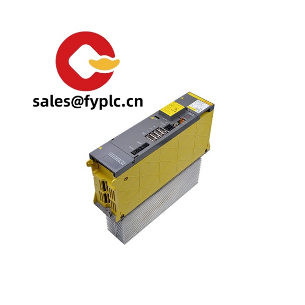
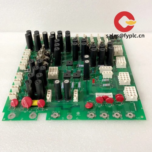
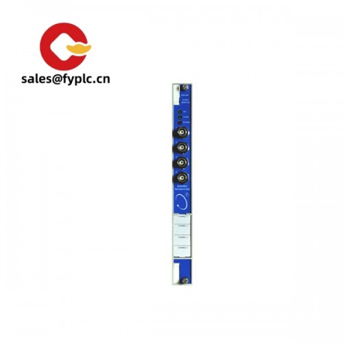
Description
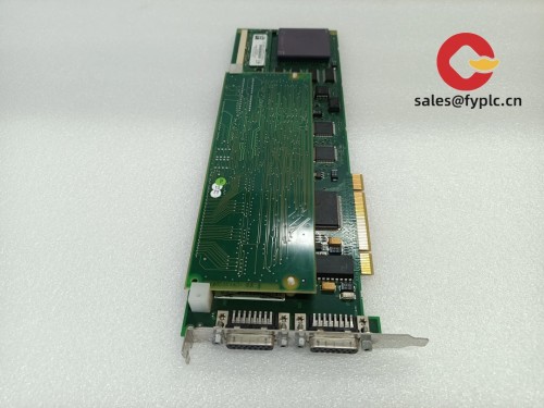
FANUC A20B-2100-0800 SPM Control Board – Drop‑in PCB for Spindle Power Module service
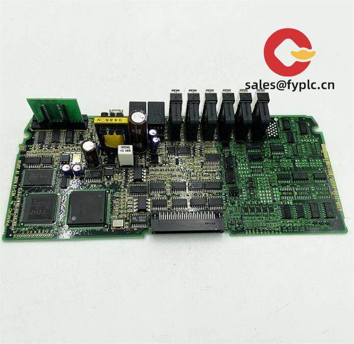
The FANUC A20B-2100-0800 SPM is a control PCB typically used inside FANUC SPM (Spindle Power Module) assemblies. From my experience, it’s a straight, plug‑in replacement board that restores stable spindle drive control without replacing the entire amplifier. You might notice that it focuses on reliable logic control, alarm handling, and signal conditioning between the CNC and the power stage, which in many cases is exactly what keeps older lines running smoothly.
Order Placement Process and Guarantees
- Warranty: 365 days
- Lead time: 1 week if in stock; no more than 1 month at the latest
- Payment: 50% advance payment; full payment prior to delivery
- Express options: FedEx, UPS, DHL
- Condition & Test: Professionally inspected and function-tested before shipment
- Packaging: ESD-safe packing, shock-protected for international transit
Key Features
- Genuine-fit form factor: Designed for SPM chassis; installs using existing standoffs and connectors.
- Stable spindle control logic: Manages speed command processing, interlocks, and alarm signaling to the CNC.
- Noise immunity: Typically conforms to FANUC’s industrial EMC practices for reliable operation around high-current IGBT stages.
- Cost-saving repair path: Often solves SPM faults without replacing the entire amplifier module.
- Traceable replacement: Clear labeling and revision info to match maintenance records and preventive service plans.
- Service-friendly: No special tools required; standard ESD handling and basic alignment checks are usually enough.
Technical Specifications
| Brand / Model | FANUC A20B-2100-0800 SPM (control PCB) |
| HS Code | 8538.90 – Parts suitable for electrical control apparatus |
| Power Requirements | Supplied by SPM backplane: +5 VDC logic (typical), with auxiliary rails as provided by the drive; low power draw |
| Dimensions & Weight | FANUC long-board format; approximately 340 × 120 mm; around 0.4–0.6 kg (typical) |
| Operating Temperature | 0 to 55°C, non‑condensing environment (typical control cabinet conditions) |
| Signal I/O Types | Logic‑level control and feedback for SPM power stage; alarm/interlock outputs; speed command and status lines within the module |
| Communication Interfaces | Internal edge connectors and ribbon harnesses within the SPM; no user‑accessible fieldbus on the PCB itself |
| Installation Method | Internal PCB, secured by standoffs; seated to the SPM backplane; ESD‑safe handling required |
Application Fields
This board is commonly found in FANUC spindle drive systems across machining centers, turning centers, grinding machines, and production cells. It’s well suited for:
- Spindle power module repairs during planned maintenance or urgent downtime recovery
- Lifecycle support on legacy FANUC CNC lines where full amplifier replacement is not ideal
- Retrofit projects aiming to keep existing spindle hardware while improving reliability
Advantages & Value
- Reliability first: In most cases, swapping this PCB resolves intermittent spindle faults tied to logic or signaling.
- Compatibility: Built for FANUC SPM assemblies, so wiring, connectors, and mounting usually match 1:1.
- Cost control: A targeted board replacement is typically more economical than a full amplifier change.
- Supportability: Easy to document for maintenance teams; clear revision markings help with future service.
A customer in automotive machining recently reported that replacing the A20B-2100-0800 stabilized spindle enable signals and cleared random SPM alarms, saving a full weekend of production. That’s the sort of outcome we see frequently when the power stage is healthy but logic control has drifted.
Installation & Maintenance
- Cabinet & environment: Install in a clean, dry control cabinet with adequate ventilation; keep ambient under 55°C.
- Power‑down procedure: Isolate mains, wait for DC bus discharge (often 5–10 minutes); verify with a meter before handling.
- ESD handling: Use an ESD wrist strap and antistatic mat; avoid touching component leads.
- Connections: Seat edge connectors firmly; inspect ribbon cables for bent pins; route away from high‑current conductors where possible.
- Post‑install checks: Run spindle at low speed first, verify alarms and temperature; confirm CNC parameters for spindle control are intact.
- Routine care: Periodically clean dust with dry, oil‑free air; check for heat discoloration or loose connectors during scheduled maintenance.
Firmware updates aren’t typically required on this board; tuning and parameters usually reside on the CNC side. If issues persist, it often points to power stage, cooling, or sensor feedback rather than the control PCB itself.
Quality & Certifications
- Manufactured under ISO 9001 quality systems (FANUC production standards)
- RoHS-compliant part sourcing where applicable
- CE/UL considerations apply at the complete machine/drive level; this is a service PCB used inside the assembly
- Backed by a 365-day warranty
Related Supporting Components
Typically paired with FANUC Spindle Power Modules (α/β series) and their gate driver boards, current sensors, and cooling assemblies. If you’re troubleshooting a persistent fault, we can also supply mating ribbon harnesses, connector kits, and compatible fan units to eliminate wiring or thermal causes.


Reviews
There are no reviews yet.