
Description
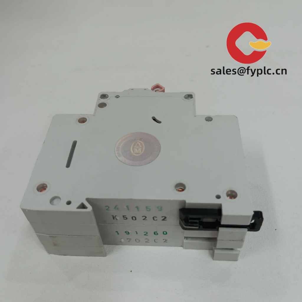
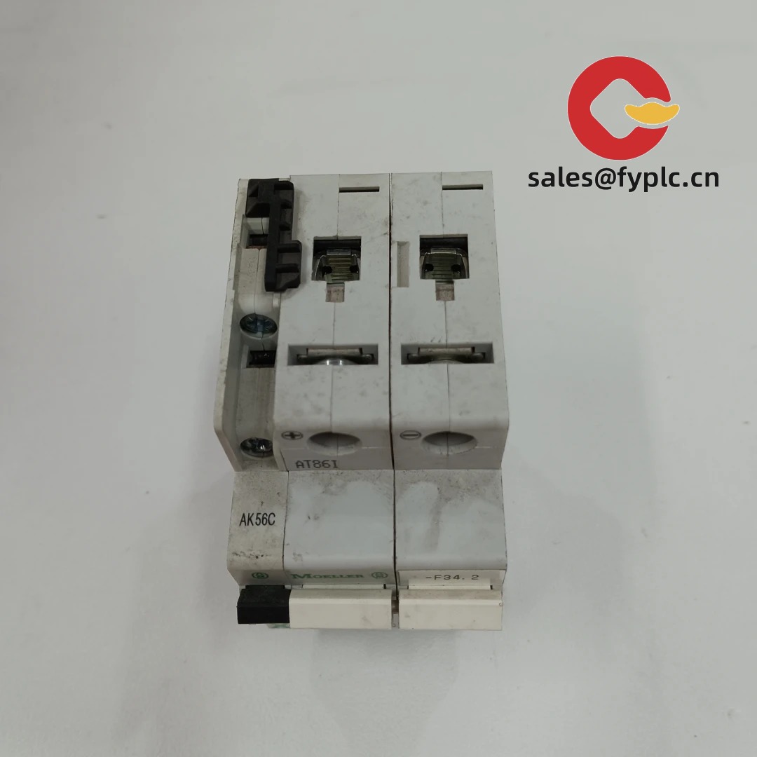
EATON PL9-C50/2-DC – Two‑Pole DC Miniature Circuit Breaker for Robust Low‑Voltage DC Protection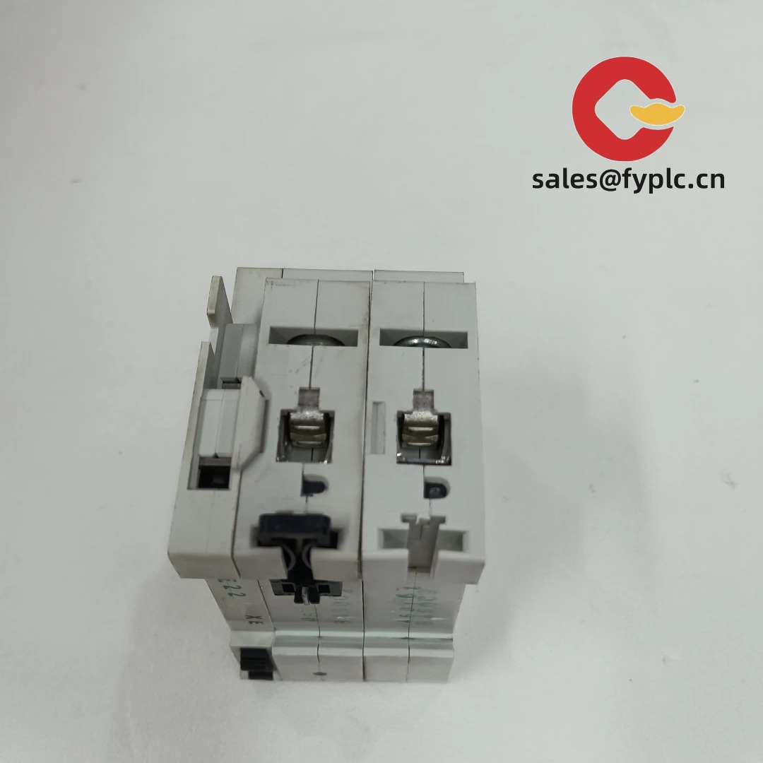
The EATON PL9-C50/2-DC is a two‑pole, C‑curve, 50 A miniature circuit breaker designed for low‑voltage DC distribution. From my experience, it fits nicely where you need dependable short‑circuit and overload protection on battery racks, DC power supplies, telecom plants, or control panels—without taking up much rail space. You might notice that it behaves predictably on inductive DC loads thanks to the C‑curve characteristic, which in many cases helps avoid nuisance trips while still reacting fast to genuine faults.
Company’s Order Placement Process and Guarantees
- Warranty: 365 days
- Delivery time: 1 week for in‑stock items; no more than one month at the latest
- Payment terms: 50% advance payment, full payment before delivery
- Express delivery methods: FedEx, UPS, DHL
Key Features
- DC‑rated, 2‑pole protection – Built for low‑voltage DC circuits where coordinated protection is needed on both polarities.
- C‑curve tripping at 50 A – Typically suitable for circuits with moderate inrush (contactors, coils, and mixed inductive loads) on DC systems.
- Compact, DIN‑rail form factor – Standard 35 mm DIN mounting for quick panel integration and easy replacement in the field.
- Clear labeling and ergonomics – Toggle is easy to identify and operate; terminals are accessible for neat wiring.
- Accessory-ready platform – In many cases compatible with xPole auxiliary contacts, shunt trip, or undervoltage release modules for remote signaling or interlocking.
- Panel safety in mind – Finger‑safe terminals and reliable terminal clamping help reduce wiring issues over time.
Technical Specifications
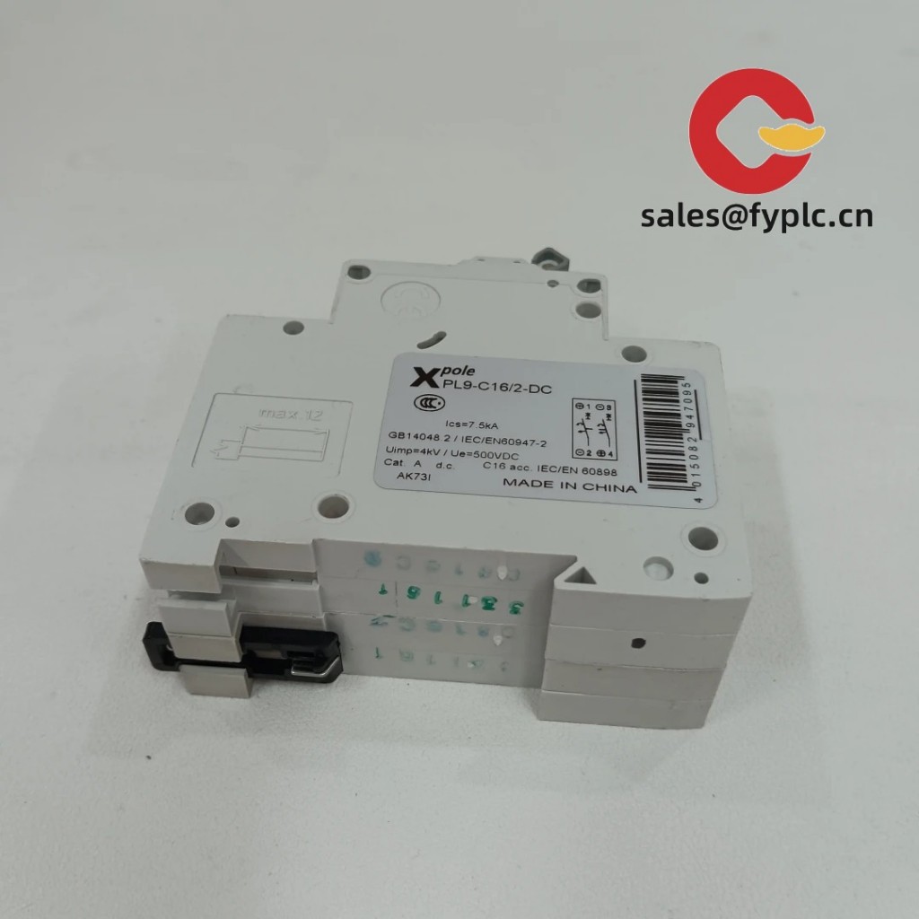
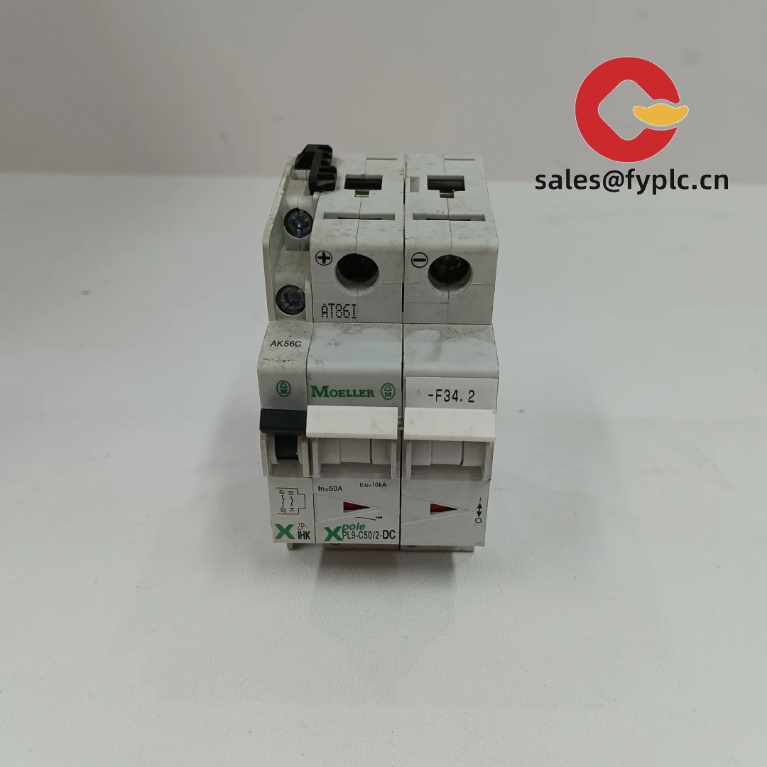
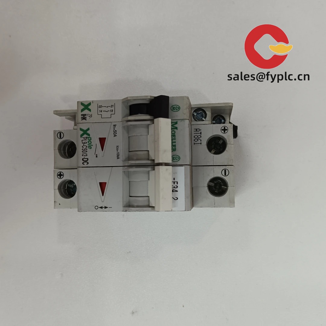
| Brand / Model | EATON PL9-C50/2-DC |
| HS Code | 8536.20.0000 (Automatic circuit breakers) |
| Rated Current | 50 A, C‑curve (MCB) |
| Poles | 2 (DC) |
| DC Operating Voltage | Application‑dependent; typically up to 250 V DC per pole. Check Eaton datasheet for series connection and derating. |
| Installation Method | 35 mm DIN rail (IEC 60715), front toggle operation |
| Terminals | Screw terminals; typically supports up to 25 mm² conductors for 50 A circuits |
| Dimensions & Weight | 2 modules (~36 mm W), approx. 83–86 mm H, ~70 mm D; ~0.25–0.30 kg |
| Operating Temperature | Typically −25 °C to +55 °C (ambient derating may apply) |
| Signal I/O Types | None on base unit; auxiliary signal contacts available on request |
| Communication Interfaces | Not applicable |
| Standards | Typically IEC/EN 60898‑1 and IEC/EN 60947‑2 compliance for xPole MCBs |
Application Fields
This model is a practical choice for low‑voltage DC distribution in:
- Battery energy storage racks (48–125 V DC ranges; higher when series‑connected poles are approved)
- Telecom power systems and rectifier outputs
- Industrial control DC buses and machine panels
- UPS DC lines and DC power supplies
- Auxiliary DC circuits in transport and process industries
One thing I appreciate is how the 2‑pole design simplifies isolating both polarities in DC cabinets. For PV string work, suitability depends on the actual system voltage and the manufacturer’s series connection rules—best to confirm the exact DC rating vs. your array voltage.
Advantages & Value
- Reliability – Stable tripping behavior and solid terminal clamping reduce rework in the field.
- Compatibility – Fits standard 35 mm rails and, in many cases, accepts xPole accessories for signaling and remote trip.
- Space efficiency – Two modules wide for 2 poles helps keep DC panels compact.
- Cost control – Using a proven Eaton platform usually lowers lifecycle costs—spares and accessories are easy to source.
- Technical support – Documentation and accessory ecosystem make approvals and maintenance straightforward.
Installation & Maintenance
- Panel environment – Mount in a closed steel cabinet with adequate ventilation; follow ambient derating above 40–45 °C.
- DIN mounting – Snap onto 35 mm rail; ensure firm seating and leave space for heat dissipation between high‑load devices where possible.
- Wiring – Use appropriately rated copper conductors (often up to 25 mm² for 50 A). Torque terminals per Eaton spec and retighten after initial thermal cycles.
- DC polarity and series use – Respect polarity markings. If series‑connecting poles to increase DC voltage rating, follow Eaton’s wiring diagram precisely; do not parallel poles to increase current.
- Selectivity – Coordinate upstream fuses/breakers to avoid nuisance tripping; check I²t and prospective fault current on the DC bus.
- Routine checks – Inspect for discoloration or hot spots, clean dust from vents and terminals, and operate the toggle periodically. No firmware or calibration is required.
A customer in a battery integration project mentioned fewer callbacks once they standardized torque values and added auxiliary contacts for panel monitoring; small things, but they help.
Quality & Certifications
- Typically complies with IEC/EN 60898‑1 and IEC/EN 60947‑2 for MCBs
- CE marking and RoHS compliance (region dependent)
- UL/CSA availability may depend on variant; please confirm if required by your project
- Manufacturer’s standard quality assurance; our warranty coverage: 365 days
Suggested Supporting Components
- Auxiliary indication contacts (open/closed status) for remote monitoring
- Shunt trip or undervoltage release modules for interlocking with E‑stop or PLC logic
- DIN‑rail busbars and end covers sized for 2‑pole MCBs to speed up assembly
- Locking devices for the toggle when lock‑out/tag‑out is required
If you share your DC bus voltage, available fault current, and ambient conditions, I can verify the exact DC rating and accessory set that best matches the PL9‑C50/2‑DC in your panel.


Reviews
There are no reviews yet.