
Description
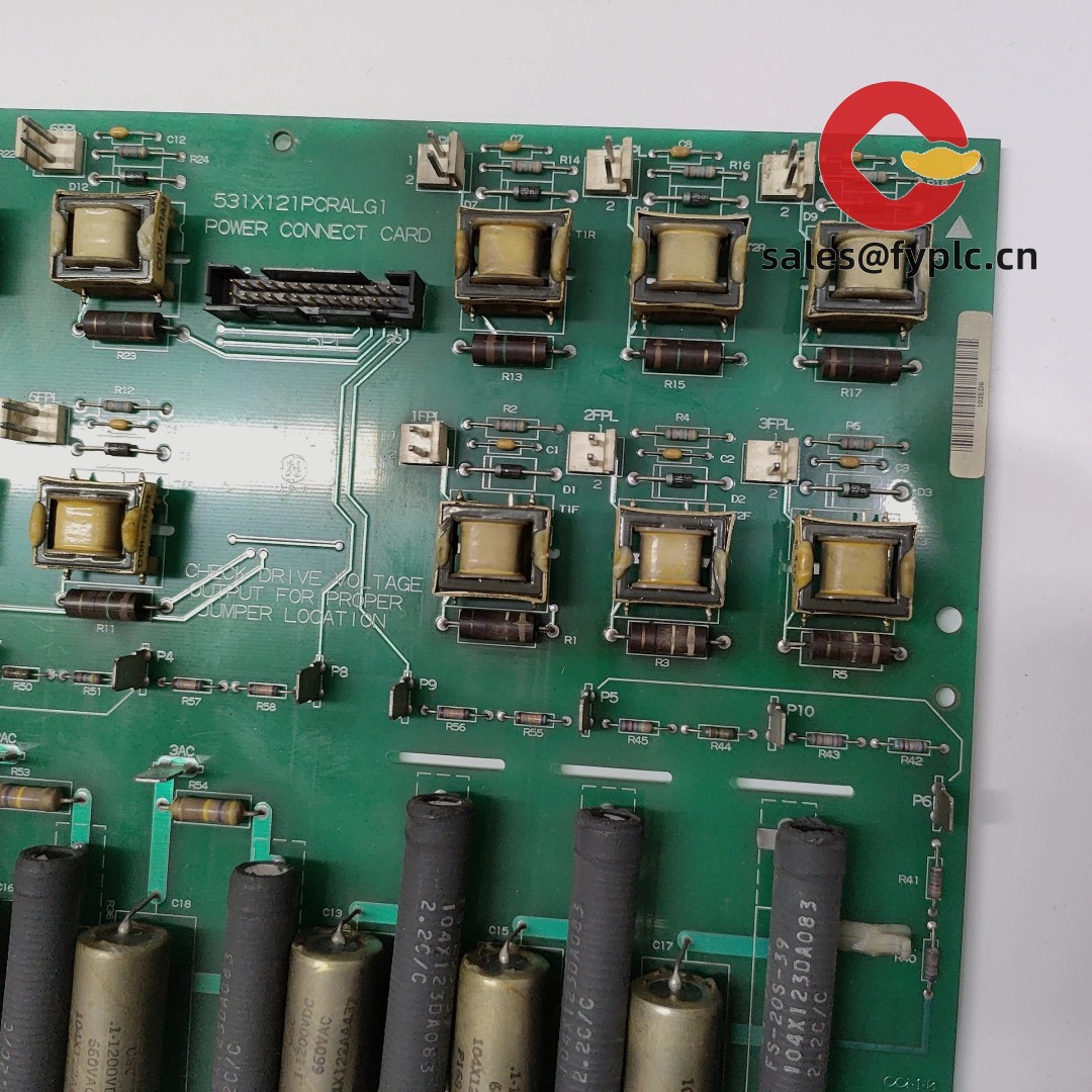
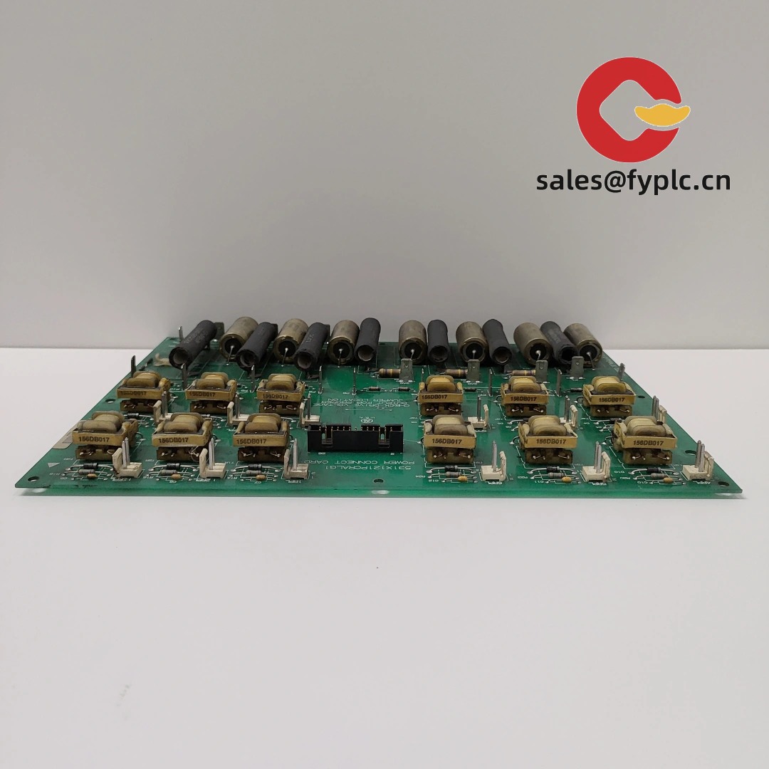
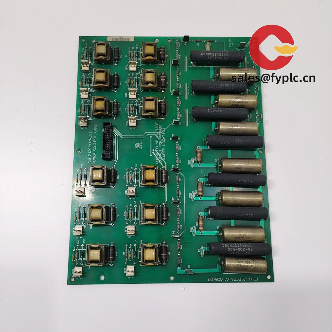
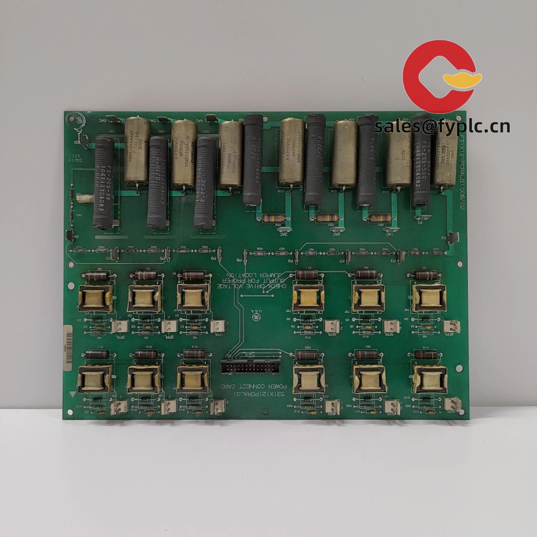
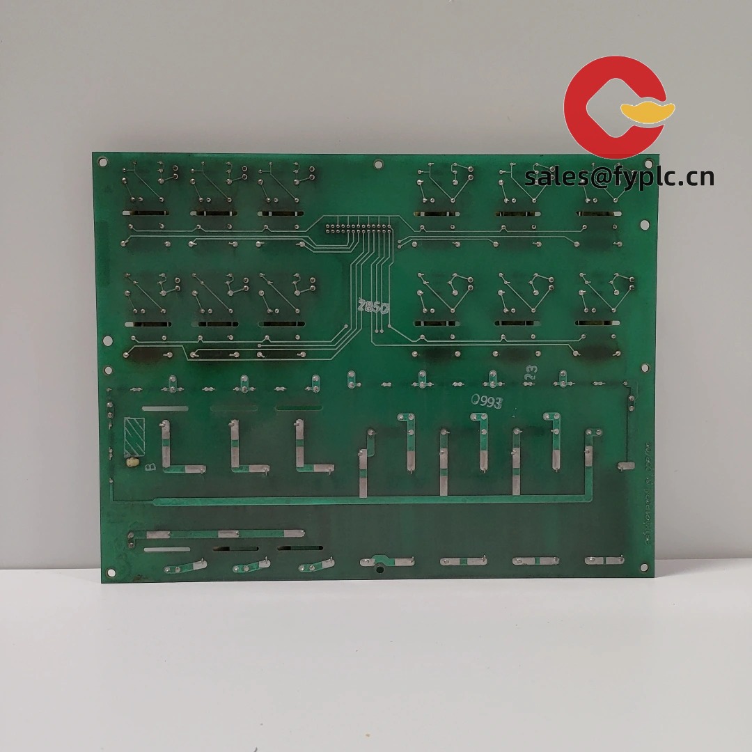
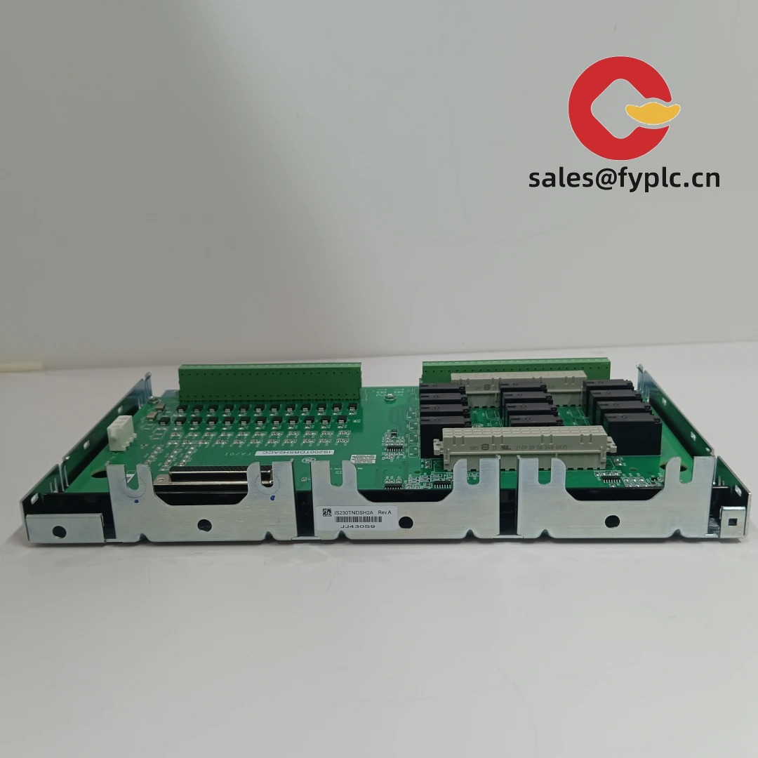
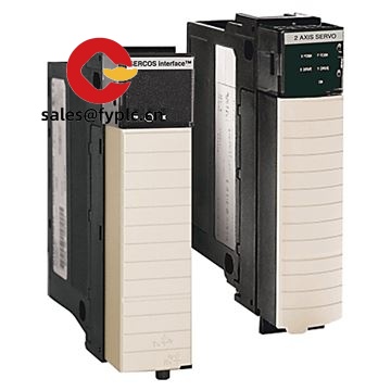
GE 531X121PCRALG1 – Process/Relay/Analog Control Board for Legacy GE Drive & Excitation Racks
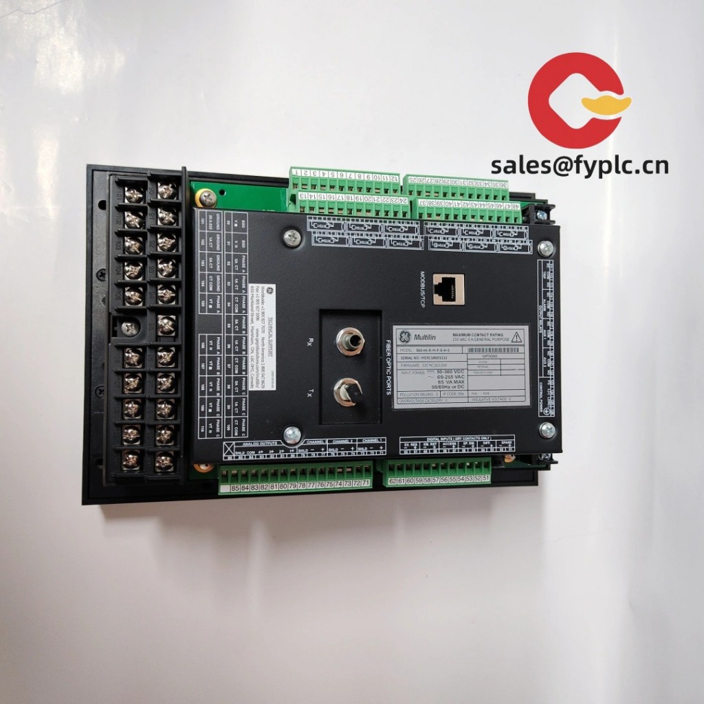
The GE 531X121PCRALG1 is a legacy control PCB from GE’s 531X series, commonly used in GE drive and exciter cabinets as a process/relay/analog interface board. From my experience, plants keep this exact G1 variant as a like‑for‑like spare to get older DC/AC drive or excitation systems running again—without touching cabinet wiring or changing proven logic. You might notice the industrial‑grade construction and labeled headers; swaps during short outage windows tend to be predictable once the backplane connector and standoffs are aligned.
Company’s Order Placement Process and Guarantees
- The warranty period is 365 days
- Delivery time: 1 week for in-stock; no more than one month at the latest
- Payment method: 50% advance payment, full payment for delivery
- Express delivery methods: FedEx, UPS, DHL
- Pre‑shipment: visual/label verification and basic functional checks; ESD‑safe, shock‑resistant packing
Key Features
- Like‑for‑like replacement – G1 build intended to drop into existing GE 531X‑based systems with minimal rework.
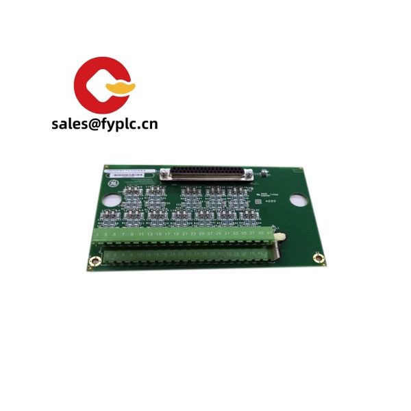
- Mixed analog/relay interface – Typically handles conditioned analog signals and relay/logic interfacing between the rack and field circuits.
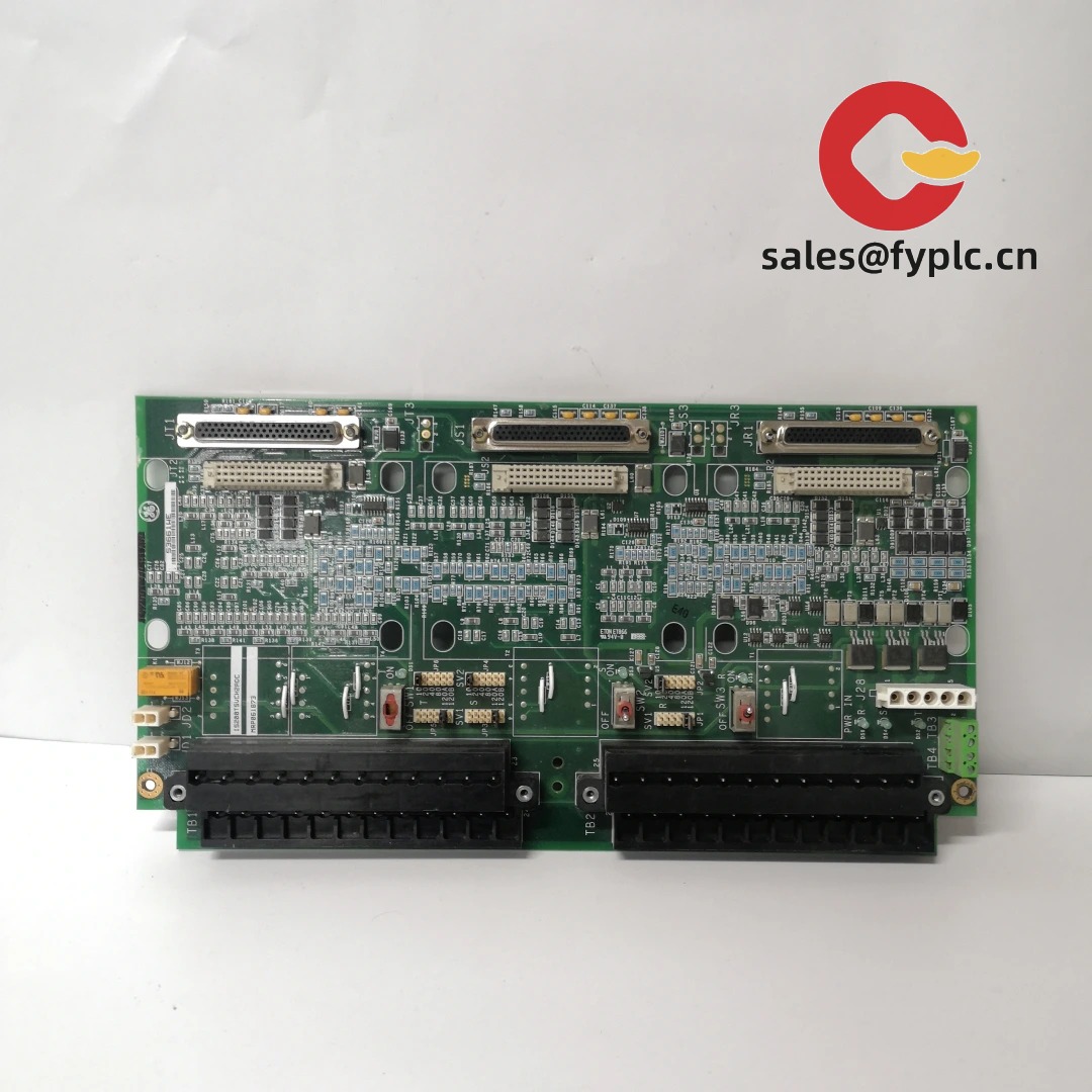
- Backplane integration – Edge connector links the card to the system bus and shared low‑voltage rails for stable operation.
- Service‑friendly layout – Labeled test points and connectors usually make diagnostics and board swaps faster.
- Rugged PCB construction – Built for 24/7 duty in drive/excitation cabinets where electrical noise and heat are common.
Technical Specifications
| Brand / Model | GE 531X121PCRALG1 |
| Series / Role | 531X legacy control board – process/relay/analog interface for GE drives/exciters (variant‑dependent) |
| HS Code (reference) | 8538.90 – Parts for electrical control equipment (final classification may vary by country) |
| Power Requirements | Supplied via rack/backplane; logic typically +5 VDC with auxiliary analog rails (e.g., ±15 V) provided by the cabinet supply |
| Signal I/O Types | Conditioned analog inputs/outputs and relay/logic points via headers/backplane (exact mix by build) |
| Communication Interfaces | Internal system backplane only (no external fieldbus on the board) |
| Dimensions & Weight (approx.) | PCB format ~300 × 200 mm; ~0.35–0.6 kg (typical for this series) |
| Operating Temperature | Typically 0…+55 °C (cabinet‑installed; non‑condensing) |
| Installation Method | Mount in GE drive/exciter rack; engage backplane edge connector; secure via standoffs and designated hardware |
Application Fields
This board shows up wherever legacy GE drive and excitation platforms are still the backbone of production:
- Steel and metals lines – coordinating DC/AC drive loops and interlocks.
- Pulp & paper – stable process control in long‑running sections.
- Power generation/exciters – cabinet spares to keep excitation systems online.
- Mining and material handling – dependable operation under electrical noise and vibration.
A maintenance lead told me last season, “We dropped in the 531X121PCRALG1, checked the backplane seating, and the drive came up clean on the first enable.” That’s typically how these swaps go when the variant matches the original card.
Advantages & Value
- Reliability – Industrial‑grade PCB design proven in 24/7 drive/excitation service.
- Compatibility – G1 build aligns with installed 531X systems, minimizing engineering changes.
- Cost savings – Extends the life of legacy assets and defers costly platform migrations.
- Support – We can help verify interchange, backplane fit, and pre‑startup checks before your window.
- Lead‑time clarity – Practical deliveries aligned with planned shutdowns.
Installation & Maintenance
- Cabinet environment: Clean, ventilated rack; ambient typically 0…55 °C; non‑condensing; avoid corrosive gases.
- ESD handling: Use a grounded wrist strap; handle by edges; store in ESD‑safe packaging.
- Seating & fixation: Align guides, fully engage the backplane connector, and tighten standoffs/screws evenly.
- Wiring & EMC: Keep analog leads and low‑level signals separate from motor power; maintain shield continuity.
- Commissioning: Verify jumpers/dip settings if present; perform a dry‑run I/O check and monitor status LEDs/diagnostics.
- Routine care: Quarterly dust cleaning, connector re‑torque, and quick trending of key analog references.
Quality & Certifications
- Manufactured to GE industrial quality standards, typically aligned with ISO 9001.
- Component‑level spare; CE/UL compliance handled at the system level in most installations.
- RoHS compliance may vary by build generation; we can confirm by part/serial.
- Warranty: 365 days repair/replace coverage from delivery.


Reviews
There are no reviews yet.