
Description
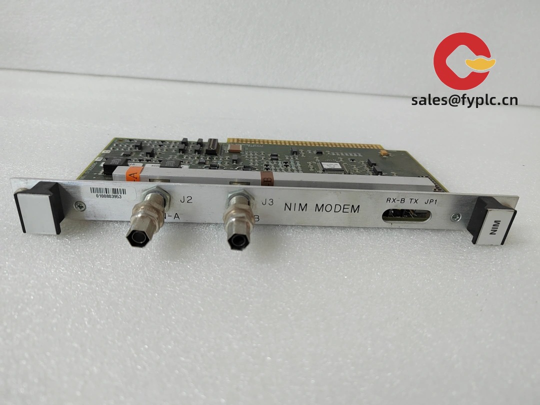
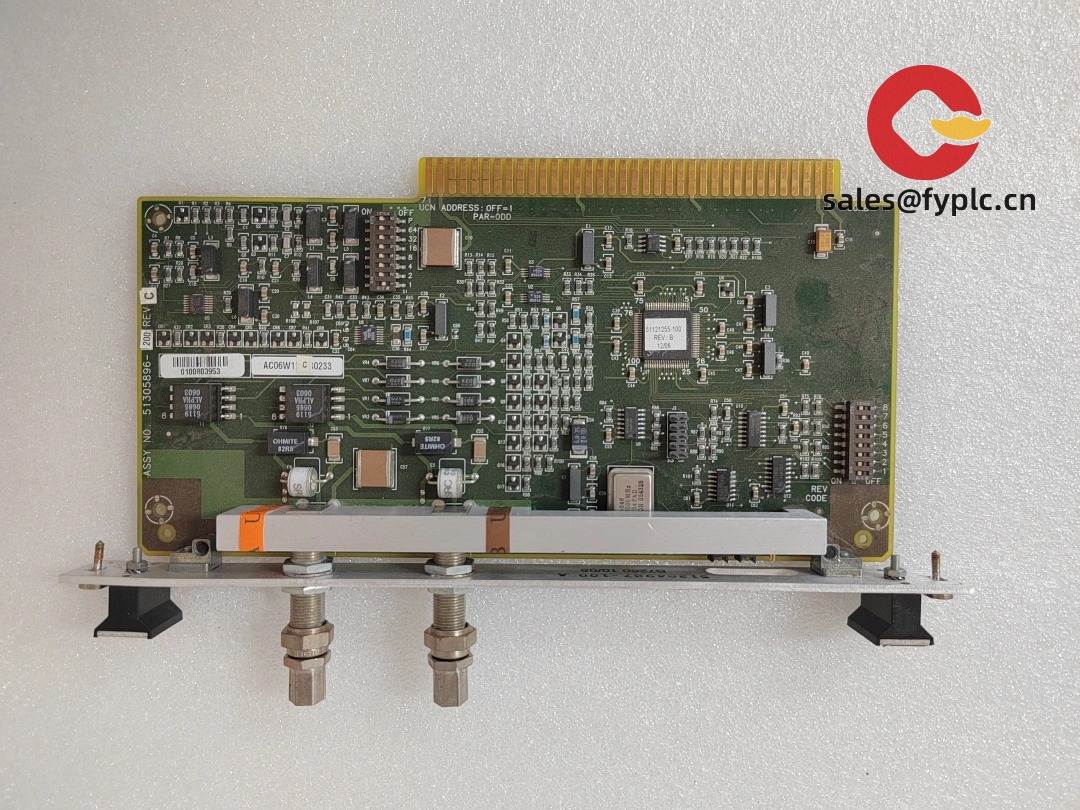
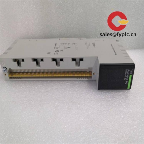
Honeywell 51305896-200 / NIM MODEM – Network Interface Module Modem Board for Legacy TDC/TPS Nodes
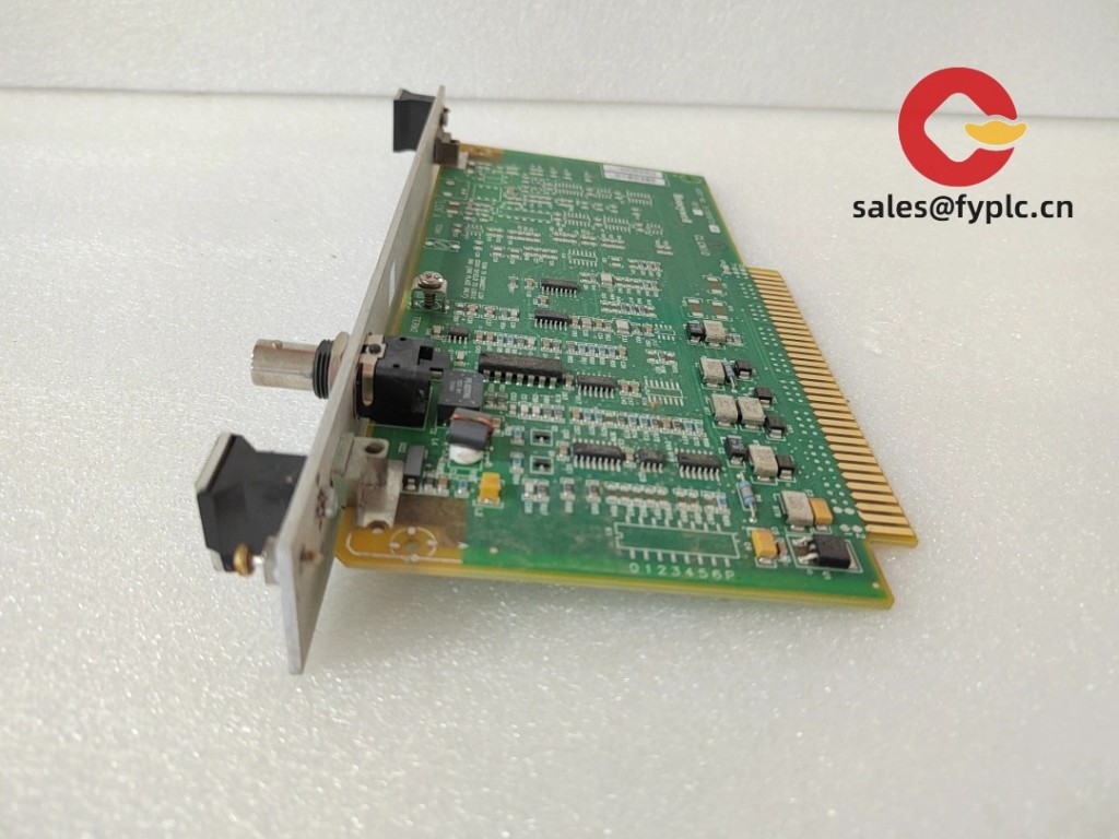
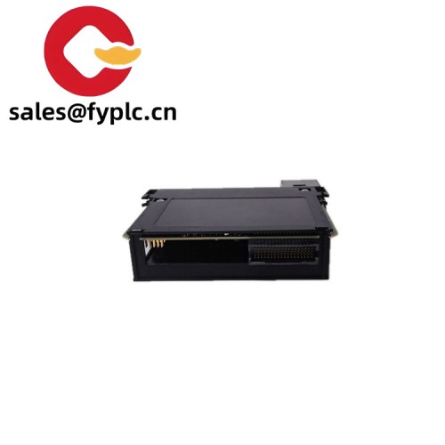
Honeywell’s 51305896-200, labeled NIM MODEM, is a modem interface board used with Network Interface Module (NIM) hardware in classic TDC 3000 / TPS installations. From my experience, plants use it to maintain dependable, long-run communications on legacy network links—often where the NIM needs a dedicated modem interface for remote connectivity or segment extension. You might notice that a like-for-like swap typically restores service without reworking cabinet wiring or node configuration, which is exactly what maintenance teams want during a tight outage.
Company’s Order Placement Process and Guarantees
- Warranty period: 365 days
- Delivery time: 1 week for in-stock; no more than 1 month at the latest
- Payment method: 50% advance payment; full payment for delivery
- Express delivery methods: FedEx, UPS, DHL
Key Features
- NIM-integrated modem interface – Provides the modem-side link for Network Interface Module communications on legacy Honeywell systems.
- Backplane powered – Draws low-voltage rails from the node chassis; no separate PSU wiring in most cases.
- Service-friendly connectors – Clearly labeled terminations/ports make it quicker to land lines and verify link status.
- Drop-in behavior – Typically replaces the existing modem board without changing cabinet wiring or node setup.
- Built for control-room duty – Stable operation under continuous use with ESD-conscious design practices.
Technical Specifications
Specs below reflect what’s commonly associated with this Honeywell board family. Share your cabinet tag, node type, and line details (2‑wire/4‑wire, interface style), and we’ll confirm the fit before shipment.
| Brand / Model | Honeywell 51305896-200 / NIM MODEM |
| HS Code | 8538.90 (Parts suitable for industrial control equipment) |
| Power Requirements | Supplied by node backplane (low-voltage logic rails); no external PSU to the board |
| Operating Temperature | Control-room ambient; typically 0 to +50/60 °C |
| Dimensions & Weight | Plug‑in module form factor for Honeywell node chassis; approx. 0.4–0.6 kg (board only) |
| Signal Input/Output Types | Line interface for modem connectivity (commonly 2‑wire/4‑wire line or RJ‑style port, revision dependent); backplane interface to NIM |
| Communication Interfaces | Modem/line side to plant telephony/leased line; internal node backplane toward the NIM |
| Installation Method | Front plug‑in to Honeywell node chassis; land modem/line wiring per drawing; set jumpers/termination as specified |
Application Fields
- TDC 3000 / TPS nodes requiring modem-linked NIM communications
- Control rooms extending legacy network links over copper/leased lines
- Brownfield sites maintaining remote access paths for diagnostics and historian links
- Spare strategies where like-for-like NIM modem boards minimize downtime
Advantages & Value
- Low integration risk – Typically a direct replacement that preserves wiring and node configuration.
- Uptime focused – Keeping a verified spare often turns a communication fault into a same‑shift recovery.
- Compatibility – Designed for Honeywell node backplanes and approved line hardware.
- Supportable lifecycle – Traceable part numbers and a 365‑day warranty fit planned outage practices.
Installation & Maintenance
- ESD handling – Use a grounded wrist strap and antistatic surface when installing or removing the board.
- Line practices – Verify the correct 2‑wire/4‑wire scheme, polarity (if applicable), and any required surge protection.
- Routing – Keep modem/line pairs away from high‑EMI cabling; maintain bend radius and strain relief.
- Commissioning – Check link status and error counters at the node; confirm modem negotiation or line stability.
- Routine checks – Inspect connectors for oxidation, re‑seat during PMs if needed, and document line topology changes.
Quality & Certifications
- UL/CE conformity typical for control room modules (revision dependent)
- RoHS status varies by vintage; we can confirm for your required build
- Manufacturer’s warranty: 12 months from shipment
Feedback from a controls specialist: “We fitted the NIM MODEM, re‑landed the line, and the node link stabilized in minutes.” If you share your node type, cabinet tag, and line details (interface and distance), we’ll validate the 51305896‑200 configuration and ship to match your maintenance window.


Reviews
There are no reviews yet.