
Description
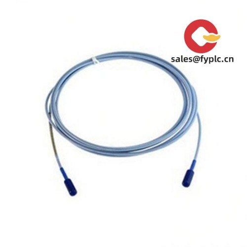
GE WES13-3 (P/N 2508-21001) – Non‑contact probe for reliable shaft position and speed feedback
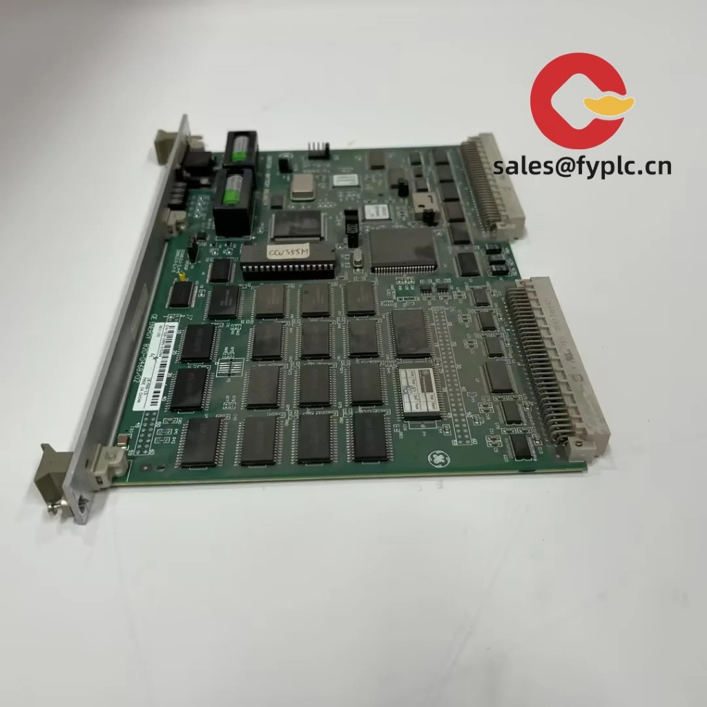
The GE WES13-3, part number 2508-21001, is a rugged, non-contact industrial probe designed for monitoring rotating machinery. From my experience, it’s typically paired with a compatible driver/monitor module to capture shaft displacement or speed-related signals without touching the target. You might notice that this design is favored in turbines, compressors, and large motors where uptime and clean signals matter more than anything else.
Company’s Order Placement Process and Guarantees
- Warranty period: 365 days
- Delivery time: 1 week for in-stock; no more than one month at the latest
- Payment method: 50% advance payment, full payment for delivery
- Express delivery methods: FedEx, UPS, DHL
Key Features
- Non-contact sensing – Reduces wear and eliminates rubbing on the rotating shaft, which typically improves reliability in continuous duty.
- Stable analog output – Works with a compatible driver/monitor to provide a consistent displacement or speed-related signal for protection systems.
- Industrial build – Shielded cable and robust probe body for harsh environments with vibration and electrical noise.
- Straightforward installation – Threaded mounting and locknut style that maintenance teams can fit with standard tools.
- System compatibility – Integrates into common condition monitoring racks and machine protection panels (proximity/“proximitor”-style drivers).
- Service-friendly – Replaceable assembly approach keeps downtime short during planned maintenance.
Technical Specifications
| Brand / Model | GE WES13-3 (Part No. 2508-21001) |
| HS Code | 9031.80 (Other measuring/checking instruments – proximity/vibration sensing) |
| Power Requirements | No separate power at the probe; powered via compatible driver/monitor module |
| Signal Input/Output Types | Analog proximity/eddy-current type signal carried over shielded coax to the driver (typical mV/µm scaling at the monitor) |
| Communication Interfaces | None at the probe; interface provided by the connected monitor/controller |
| Operating Temperature | Typically suitable for industrial environments; verify exact rating per build and mounting location |
| Dimensions & Weight | Compact probe with integrated cable; assembly length and tip style as supplied for the application |
| Installation Method | Threaded probe mounting with locknut; shielded cable routed to driver/monitor in the control cabinet |
Application Fields
This kind of probe is widely used on steam and gas turbines, centrifugal compressors, fans, pumps, gearboxes, and large generators. In many cases, plants deploy it for:
- Shaft vibration and relative displacement monitoring for trip/protection logic
- Axial position or thrust bearing movement trending
- Keyphasor/once-per-rev timing and speed feedback (with appropriate target and monitor)
- Condition monitoring programs where repeatable gap and stable output are essential
One thing I appreciate is how maintenance teams can standardize across multiple machines. A site engineer told us they swapped a WES13-3 assembly during a minor outage and immediately saw cleaner orbits on the monitor—less drift compared to the worn unit they removed.
Advantages & Value
- Reliability – Non-contact sensing avoids mechanical wear and usually extends service intervals.
- Compatibility – Works with standard proximity probe drivers/monitors, simplifying spares strategy.
- Lower lifecycle cost – Simple installation and predictable output reduce troubleshooting time.
- Support and availability – We can help match the probe to your driver and target material to reduce setup headaches.
- Risk reduction – Stable signals feed protection systems that prevent costly trips and secondary damage.
Installation & Maintenance
- Mounting – Install the threaded probe perpendicular to the shaft surface; set the nominal gap at the monitor per procedure, then lock the nut.
- Wiring – Route shielded cable separately from high-voltage lines; maintain minimum bend radius and keep connectors clean and dry.
- Cabinet environment – Place the driver/monitor in a ventilated cabinet; typical control panel wiring and grounding practices apply.
- Safety – Lockout-tagout before any work near rotating parts; verify zero energy and allow hot sections to cool.
- Routine checks – Inspect cable and connectors quarterly; wipe the probe face if contamination builds up; verify gap and bias at the monitor after major outages.
- Calibration/verification – Perform a system check with known shims or target movement to confirm scale at the monitor (typically done after replacement or annually).
Quality & Certifications
- Manufacturing aligned with ISO 9001 quality systems (typical for this product category)
- CE and RoHS applicability generally tied to the complete monitoring system; we can help confirm for your build
- UL/CSA recognition may apply at the system level; check your panel certification needs
- Manufacturer’s warranty terms vary by region; our supplied units carry a 365‑day warranty
If you’re replacing an existing probe or building a spares kit, share the driver/monitor model and the required cable length. That small detail typically ensures you get a drop‑in fit and the expected bias/gap performance on day one.


Reviews
There are no reviews yet.