
Description
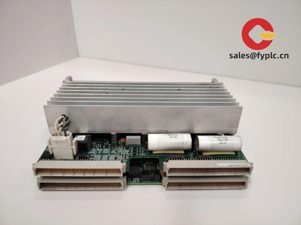
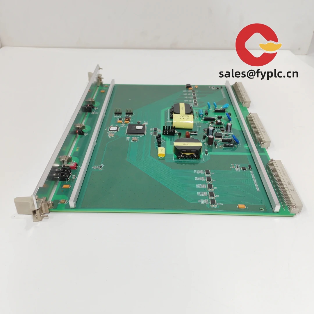
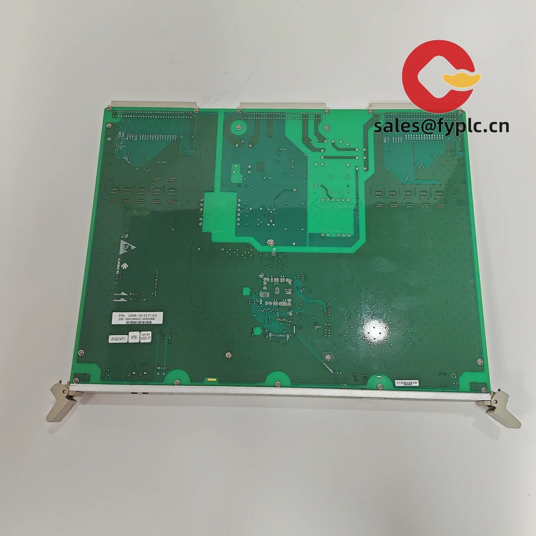
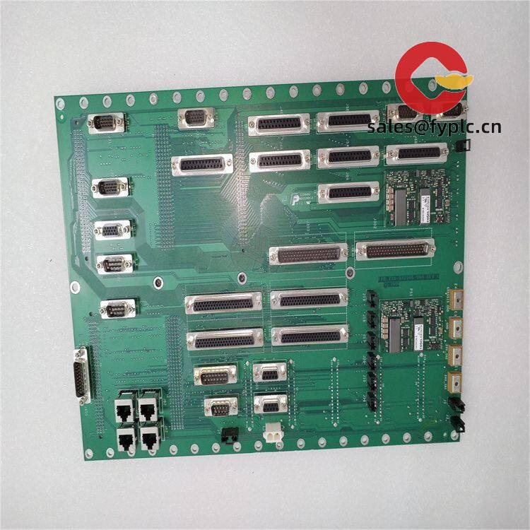
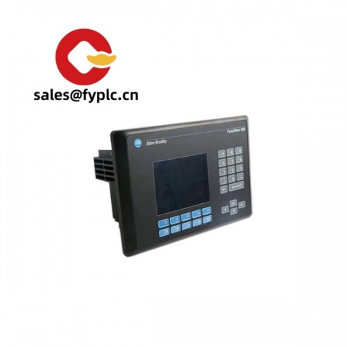
VPS Series – VPS_12004-102-03_V1.0.0 industrial protection/monitoring module for control cabinets
The VPS_12004-102-03_V1.0.0 is a compact industrial module typically used for condition monitoring and protection logic in control panels. From my experience, this VPS variant slots in neatly on a DIN rail, takes a stable 24 VDC supply, and bridges sensors to plant controls through simple relays or Modbus. You might notice that the version tag “V1.0.0” aligns with a stable, baseline firmware—ideal for replacement projects where you want consistent behavior across units.
Company’s Order Placement Process and Guarantees
- Warranty: 365 days
- Delivery time: 1 week if in stock; no more than one month at the latest
- Payment terms: 50% advance payment; full payment prior to delivery
- Express options: FedEx, UPS, DHL
One thing I appreciate is the predictability—most replacement orders ship quickly, and we pre-check firmware revision against your requirement to avoid mismatches onsite.
Key Features
- 24 VDC control power – Designed for standard cabinet supplies; typically tolerant to 18–30 VDC.
- Mixed signal I/O – Accepts common industrial sensor signals and exposes clean relay outputs for alarms or trips.
- RS‑485 (Modbus RTU) integration – In many cases used for data collection or remote parameter checks from the PLC/SCADA side.
- DIN‑rail friendly footprint – Saves panel space and speeds up swap‑outs during maintenance.
- Firmware V1.0.0 – Stable baseline behavior; good choice for like‑for‑like replacements across a fleet.
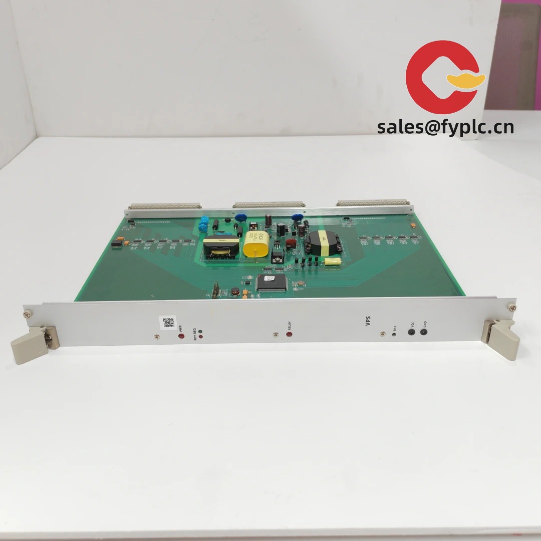
- Service/update port – Typically a front‑access service interface for configuration or firmware refresh.
- Field‑proven reliability – Teams report fewer nuisance trips compared to mixed third‑party modules.
Technical Specifications
| Brand / Model | VPS Series / VPS_12004-102-03_V1.0.0 |
| HS Code | 8538.90 (Parts for electrical control apparatus; final classification may vary by jurisdiction) |
| Power Requirements | 24 VDC nominal (typ. 18–30 VDC), ≤10 W in most cases |
| Operating Temperature | -20°C to +60°C (typical control cabinet environment) |
| Signal Input/Output Types | Analog inputs (e.g., 4–20 mA), digital inputs (24 VDC), relay outputs (alarm/trip) |
| Communication Interfaces | RS‑485 (Modbus RTU); service/configuration port for firmware update |
| Installation Method | DIN‑rail mounting; panel mount option in many cabinets |
| Dimensions & Weight | Compact DIN‑rail module footprint; lightweight (<0.5 kg) |
| Firmware | V1.0.0 (field‑stable baseline) |
Application Fields
This model is commonly adopted in rotating equipment protection (pumps, fans, compressors), conveying lines, and general machine safeguarding where sensor inputs must trigger deterministic alarms or shutdowns. A typical setup is: 4–20 mA vibration or temperature into the module, alarm thresholds set via software, dry‑contact relays wired to the PLC E‑stop loop, and RS‑485 into SCADA for trending. A maintenance lead from a food plant told us, “After swapping in the VPS_12004-102-03_V1.0.0, our conveyor stopped throwing nuisance faults during washdown, which saved us several unplanned stops per week.”
Advantages & Value
- Reliability in real cabinets – Appears to be quite tolerant to electrical noise when properly grounded and shielded.
- Compatibility – Works smoothly with mainstream PLCs over RS‑485/Modbus; relay outputs drop into existing alarm circuits.
- Cost control – Reduces nuisance trips and technician call‑outs, which in many cases pays back faster than expected.
- Support & stocking – We align firmware revision and terminal layout before shipping so your onsite install is plug‑and‑play.
Installation & Maintenance
Panel/cabinet: Mount on 35 mm DIN rail inside a ventilated cabinet (IP54 or better recommended). Allow ~50 mm clearance for airflow.
Power & grounding: 24 VDC supply via a dedicated, fused feed. Bond PE ground to the cabinet ground bar. Keep analog and power wiring separated.
Wiring: Use shielded twisted pairs for 4–20 mA signals; terminate RS‑485 with 120 Ω at the bus ends; maintain common reference to avoid ground loops.
Safety: De‑energize before servicing. Verify alarm/trip logic in a safe test mode prior to putting the machine back into service.
Routine maintenance: Quarterly check of terminal tightness, dust removal with dry air, verify alarm thresholds, and—if applicable—apply non‑disruptive firmware updates via the service port.
Quality & Certifications
- CE compliance for EMC and LVD (typical for this class of control modules)
- RoHS conformant materials
- Manufactured under ISO 9001 quality systems
- Warranty: 365 days
Common Supporting Components
- 24 VDC panel power supply (e.g., 60 W) with DIN‑rail clip
- DIN‑rail end clamps and grounding terminals
- RS‑485 to USB converter for commissioning
- Shielded signal cable (2‑pair, 22 AWG) for analog inputs


Reviews
There are no reviews yet.