
Description
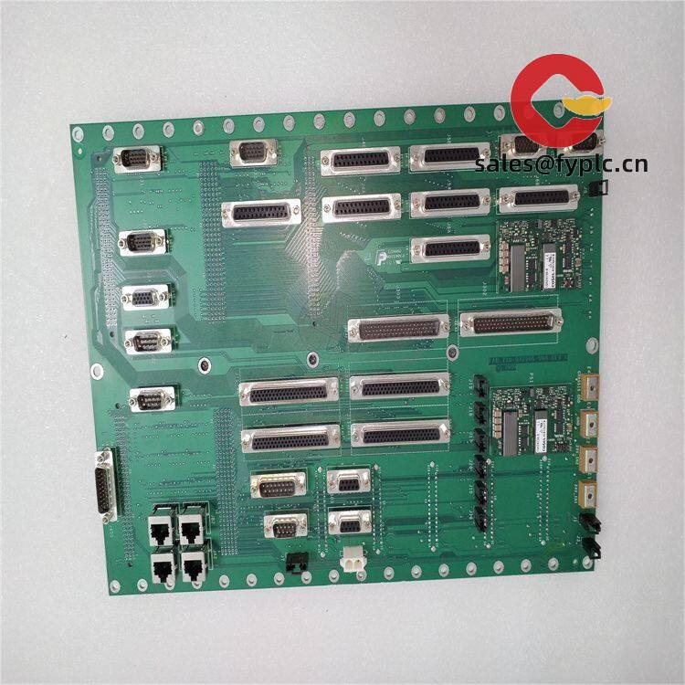
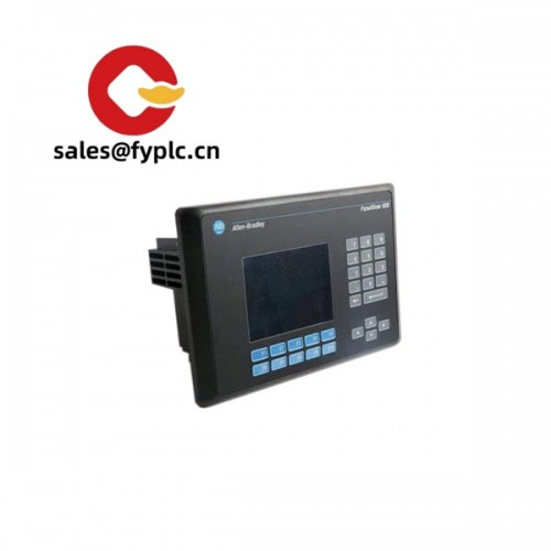
EATON CS-TX3-3.-81X2.54-64TW – High‑density 2.54 mm PCB Connector for Control & I/O Harnessing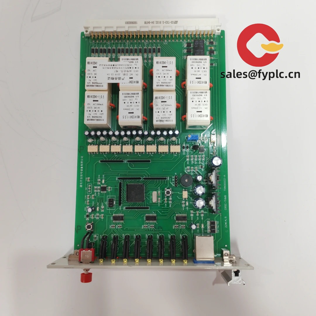
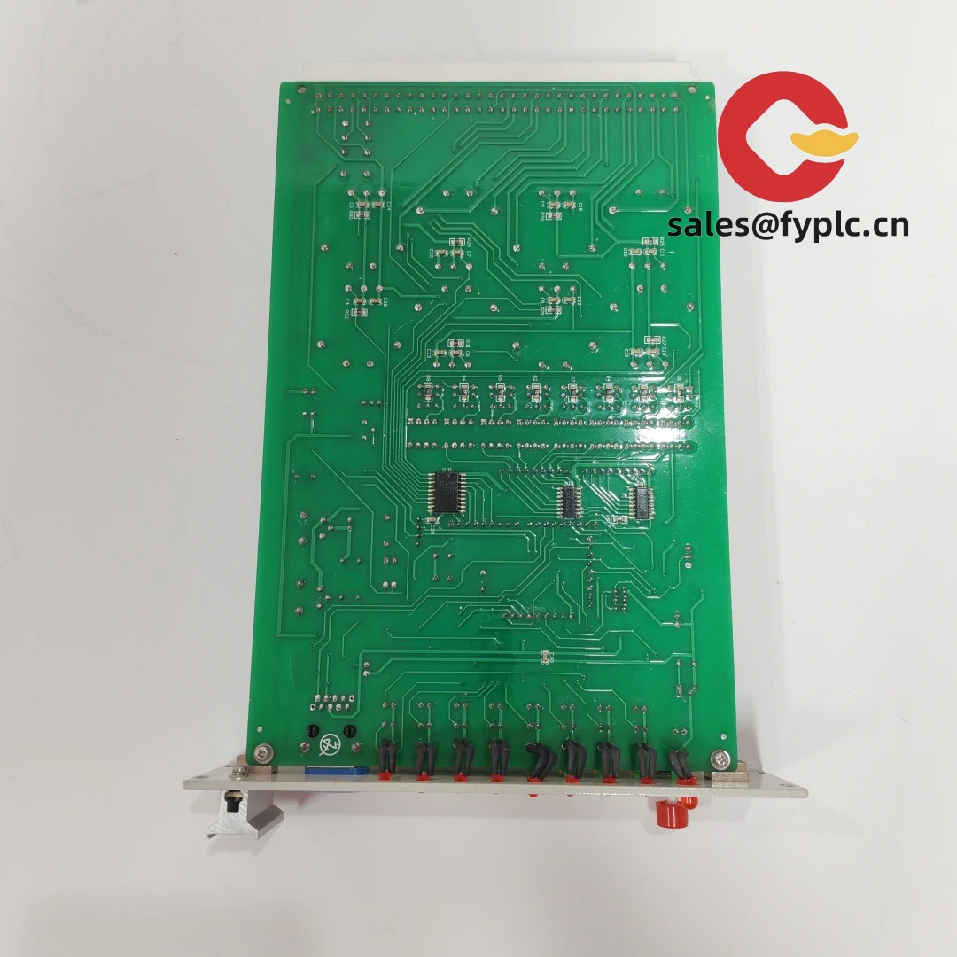
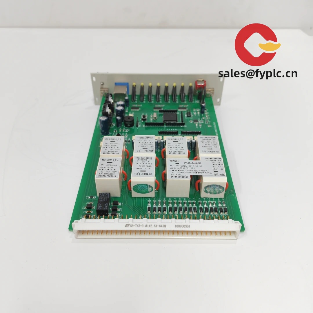
From my experience, the model CS‑TX3‑3.-81X2.54‑64TW is designed for dense board connections where standard 2.54 mm pitch is preferred, and 64 circuits are needed without taking too much space. It seems to be a through‑hole, board‑mounted connector intended for signal distribution on PLC I/O boards, motion controllers, test jigs, or interface cards. One thing I appreciate is the familiar 2.54 mm pitch — it typically keeps it compatible with a wide range of mating headers and harnesses you already use on the line.
Company’s Order Placement Process and Guarantees
- Warranty: 365 days
- Lead time: 1 week if in stock; no more than one month at the latest
- Payment terms: 50% advance payment; full payment before delivery
- Express options: FedEx, UPS, DHL
Key Features
- 2.54 mm standard pitch: Typically ensures broad compatibility with legacy boards, fixtures, and standard ribbon harnesses.
- 64 positions: High circuit density for compact I/O groups on PLC slices or DAQ cards, reducing connector count.
- Through‑hole mounting: Suited for robust wave‑solder processes and mechanically stable in high‑vibration cabinets.
- Industrial temperature capability: In many cases supports −40 to +105°C operation for typical factory floor environments.
- Serviceable and easy to inspect: You might notice solder joints are accessible for visual inspection and rework when needed.
- Neutral to protocol: Works with digital I/O, low‑voltage analog, and field wiring fan‑outs since it’s a passive connector.
Technical Specifications
| Brand / Model | EATON/ CS-TX3-3.-81X2.54-64TW |
| HS Code | 8536.69 (Electrical connectors, for a voltage ≤1000 V) |
| Power Requirements | Passive component; no external power required |
| Positions & Pitch | 64 positions, 2.54 mm pitch |
| Dimensions & Weight | Length typically ~162 mm at 64P/2.54 mm; lightweight (<30 g). Exact drawing available on request. |
| Operating Temperature | Typically −40°C to +105°C |
| Signal I/O Types | Low‑voltage digital and analog signals; low‑current power distribution (application‑dependent) |
| Communication Interfaces | N/A (passive connector; protocol‑agnostic) |
| Installation Method | Through‑hole PCB mount; wave solder recommended |
Application Fields
This model fits nicely in control cabinets and test equipment where dense, reliable board connections are needed:
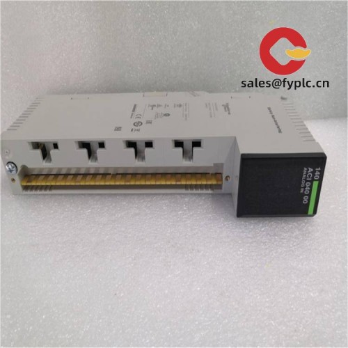
- PLC and DCS I/O cards consolidating 16–64 channels per slice
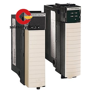
- Motion control and drives signal harnessing (encoders, limit switches, reference signals)
- Data acquisition and laboratory instruments using standard 2.54 mm headers
- Functional test fixtures and burn‑in boards that swap connectors frequently
- Communication breakout boards (protocol‑neutral fan‑outs for RS‑level or GPIO signals)
A customer in automotive test noted the 64‑way 2.54 mm format “made loom changes painless” during fixture revisions, which, in many cases, saves hours per iteration.
Advantages & Value
- Compatibility: Standard 2.54 mm ecosystem reduces custom parts and keeps spares easy to source.
- Reliability: Through‑hole soldering provides mechanical strength under vibration and repeated mating.
- Cost control: Consolidating to 64 circuits per connector typically lowers PCB real estate and harness complexity.
- Risk reduction: Passive, protocol‑agnostic design avoids lock‑in and assists cross‑platform use.
- Support: Drawings and application guidance available to align pinout, creepage/clearance, and solder process.
Installation & Maintenance
- Cabinet & environment: Install in a ventilated enclosure to keep temperature within −40…+105°C; avoid condensation.
- PCB layout: Use 2.54 mm grid; provide adequate annular ring and solder‑thru hole tolerance for wave solder.
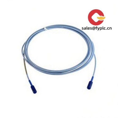
- Wiring & strain relief: Route cable bundles to avoid side‑loading the connector; add lacing/strain relief where needed.
- Solder process: Wave solder is recommended for consistent fill; verify with IPC‑A‑610 criteria.
- Safety: De‑energize circuits before mating/unmating; follow ESD handling if sensitive signals are present.
- Routine care: Periodically inspect joints and contact surfaces; clean light debris with IPA swabs; check retention after service.
- Documentation: Keep the latest drawing/revision aligned with your BOM; request sample before mass run if stack‑up is tight.
Quality & Certifications
- Typically supplied RoHS compliant; UL recognition is common for connector families in this class
- Manufacturer’s warranty support applies; our warranty coverage is 365 days
- Compliance documents (RoHS/REACH declarations, material data) available upon request
If you need the exact mechanical drawing, recommended hole size, or a mating part suggestion (straight vs. right‑angle, tin vs. gold), share your stack‑up and we’ll match the spec so it fits the first time.


Reviews
There are no reviews yet.