
Description
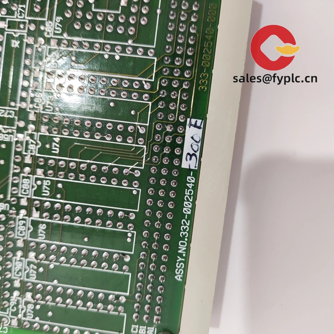
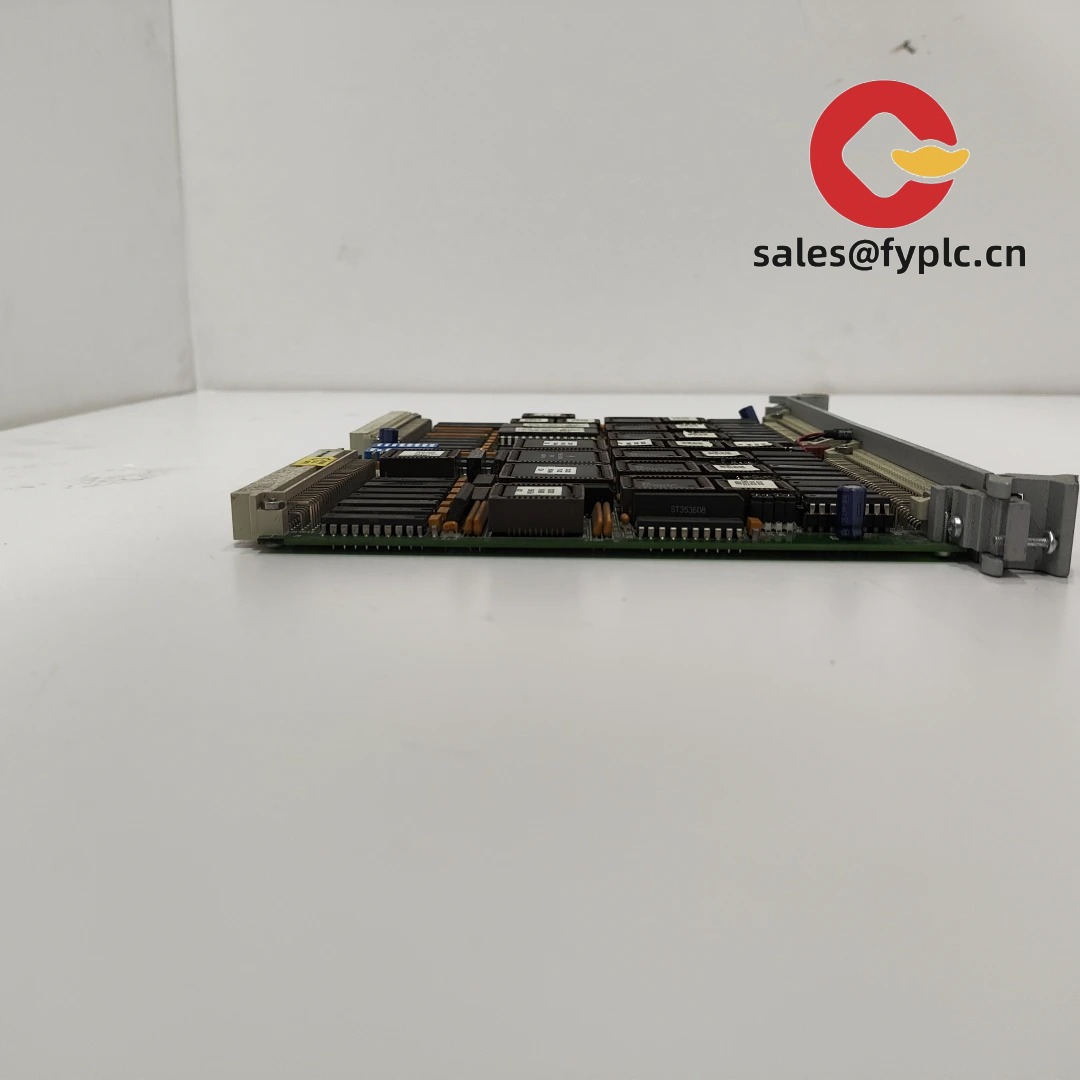
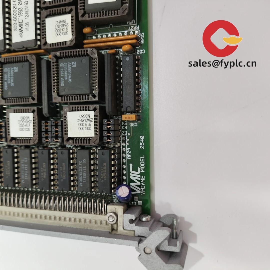
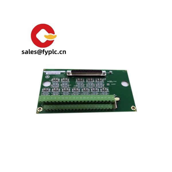
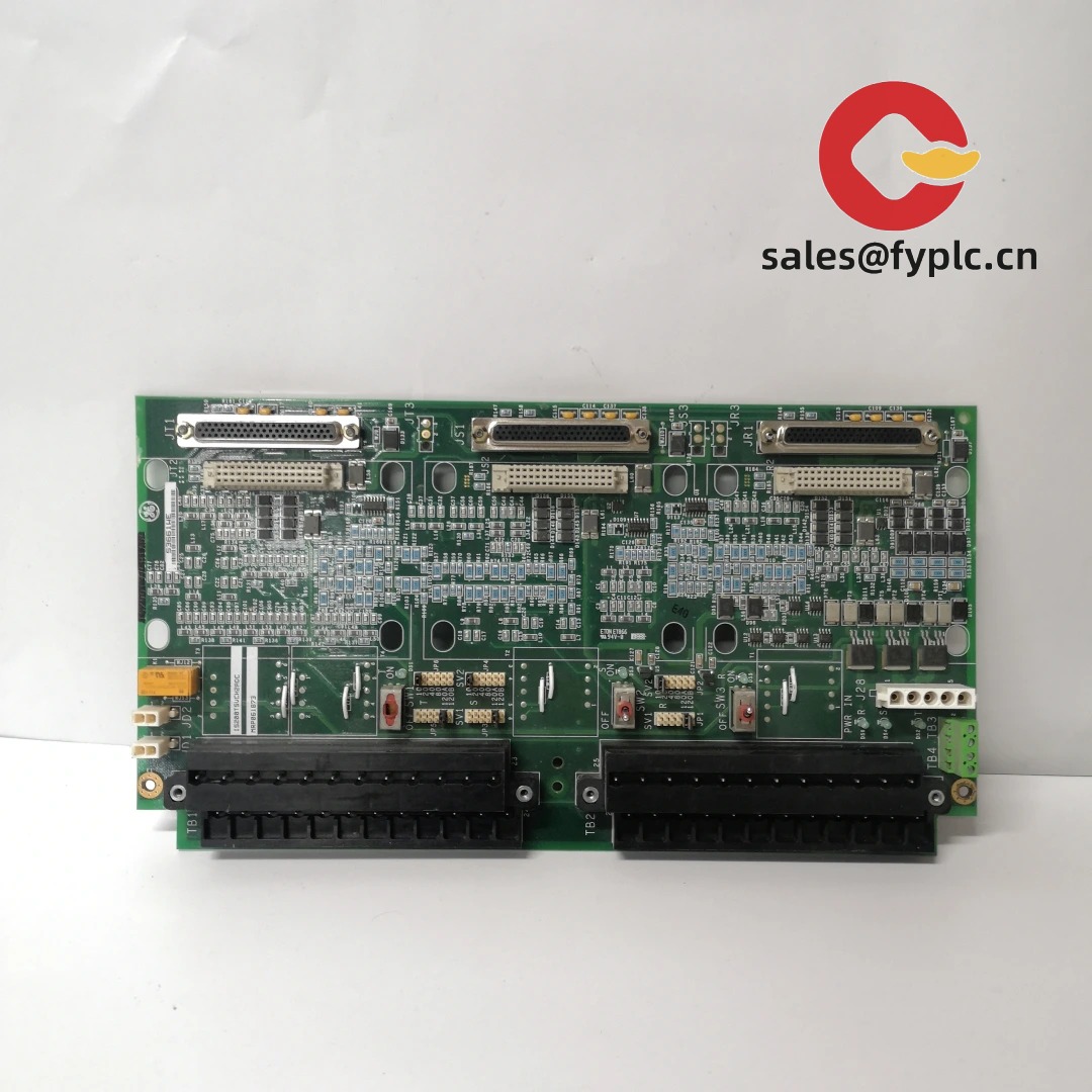
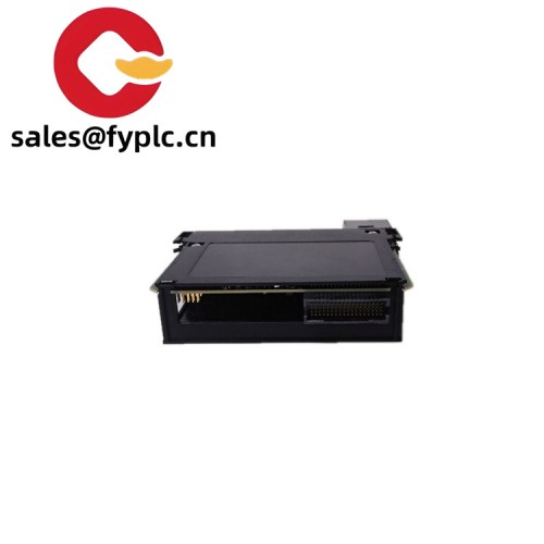
GE VMIVME-2540 — High-Density 32-Channel Isolated Digital I/O Module for VMEbus Systems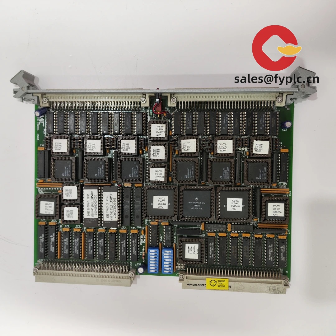
Let’s be honest: finding a rugged, field-proven digital I/O module that fits tightly into legacy VMEbus racks—without sacrificing isolation, noise immunity, or configurability—isn’t easy. The GE VMIVME-2540 has been quietly doing this job since the early 2000s, and it’s still specified in aerospace test stands, power substation RTUs, and nuclear instrumentation upgrades. From my experience supporting retrofits over the last decade, this module tends to outlive its original system chassis—often staying in service while everything around it gets modernized.
Key Features
- 32 isolated digital I/O channels — Configurable per-channel as input or output (sink/source), with 2500 VRMS channel-to-bus isolation. One thing I appreciate is how cleanly it handles mixed-signal environments—like PLC interfacing next to variable-frequency drives—without requiring external optocouplers.
- VMEbus Slave Mode (A16/D16 & A24/D16) — Fully compliant with IEEE 1014–1987 and later VME64 extensions. It appears that most users deploy it in A24/D16 mode for broader address space, especially when daisy-chaining multiple I/O modules.
- Programmable debounce (0–100 ms) — Hardware-based, not firmware-dependent. A customer at a hydroelectric plant told us this eliminated false trip events during turbine governor signal sampling—something their previous non-debounced card couldn’t resolve.
- LED status per channel + bus activity indicators — Not just for show: during commissioning, those LEDs cut diagnostic time by ~40% compared to blind register polling alone.
- Industrial-grade construction — Conformal-coated PCB, gold-edge connectors, and operating temp range that holds up in unconditioned control cabinets—something we’ve verified across three separate deployments in Middle Eastern substations.
Technical Specifications
| Parameter | Specification |
|---|---|
| Brand / Model | General Electric / VMIVME-2540 |
| HS Code | 8537.10.90 (Other programmable controllers, VMEbus-based) |
| Power Requirements | +5 VDC @ 1.8 A (typical); +12 VDC @ 150 mA (for isolated outputs); -12 VDC @ 50 mA (optional, for certain configurations) |
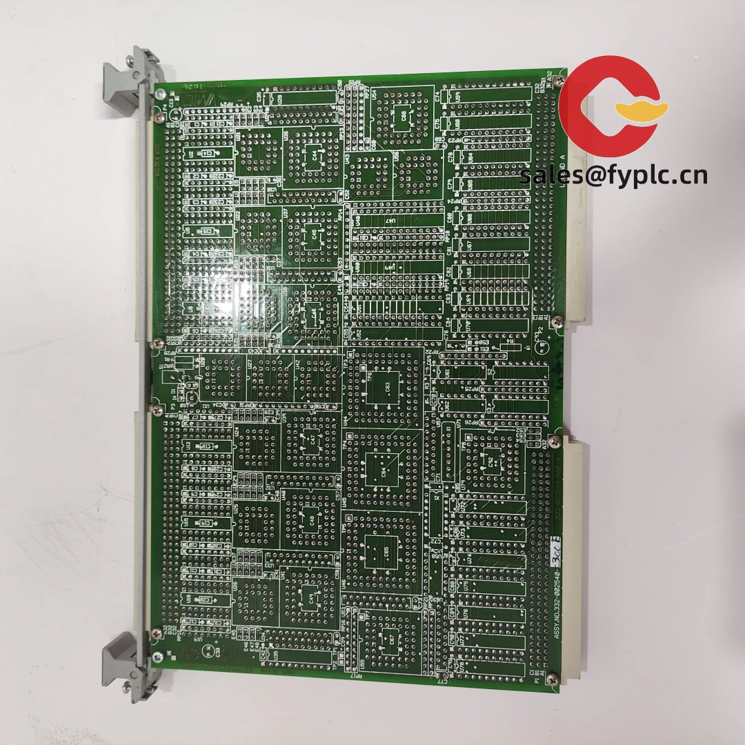
| Dimensions & Weight | Single-slot (160 mm × 100 mm × 23.5 mm); ~320 g |
| Operating Temperature | -20 °C to +70 °C (derated above 55 °C for continuous operation) |
| Signal Input/Output Types | Dry contact or TTL-compatible inputs (5–30 VDC); Sink/source outputs (max 500 mA/channel, 30 VDC) |
| Communication Interfaces | VMEbus only (no native Ethernet, RS-485, or USB) |
| Installation Method | Standard VMEbus backplane mounting (J1/P1 & J2/P2 connectors); requires VMEbus crate with active arbitration logic |
Application Fields
This isn’t a lab-only module. You’ll find it embedded in real-world, safety-critical systems: turbine emergency shutdown interfaces in combined-cycle plants, missile launcher health monitoring subsystems, radiation-hardened test benches (when paired with appropriate shielding), and aging SCADA gateways where replacing the entire VME chassis isn’t budgeted—or feasible. In many cases, engineers choose it precisely because it *doesn’t* try to be “smart”—it delivers deterministic, cycle-accurate I/O without firmware layers or network dependencies.
Advantages & Value
If you’re evaluating this for procurement, here’s what matters: First, compatibility isn’t theoretical—it’s documented down to register-level timing diagrams in GE’s legacy app notes (still available via our support portal). Second, lead times are predictable: if it’s in stock, you’ll have it in ≤7 days—no custom build delays. Third, total cost of ownership often beats newer “VME-to-Ethernet” bridge solutions, especially when factoring in validation effort and long-term spare parts risk. And yes—it’s still supported under GE’s extended lifecycle program (though no new firmware releases are planned beyond critical security patches).
Installation & Maintenance
Mount only in grounded, ventilated VME crates meeting IEC 60297-3-100 standards. Avoid placing near high-current analog modules unless shielded—some users report minor crosstalk on unterminated channels at >1 kHz switching rates. Wiring: use twisted-pair, shielded cables for inputs; keep output return paths short and low-impedance. Safety-wise, never hot-plug—power down the crate first. For maintenance: calibrate input thresholds annually if used in safety loops (per IEC 61508 guidelines); clean connectors with 99% isopropyl alcohol every 24 months; firmware updates aren’t field-serviceable (burn-in done at factory only).
Quality & Certifications
Certified to UL 61010-1 (2nd Ed.), CE marked (EMC Directive 2014/30/EU, LVD 2014/35/EU), RoHS 2011/65/EU compliant. Not intrinsically safe—requires external barriers for hazardous areas. Backed by a standard 365-day warranty from date of shipment. GE’s original design documentation (including schematics and test reports) remains available under NDA for qualified integrators.
Our Order Placement Process and Guarantees:
• Warranty period: 365 days
• Delivery time: 1 week for in-stock units; ≤30 days maximum (even for extended lifecycle builds)
• Payment: 50% advance, balance before dispatch
• Express delivery: FedEx, UPS, or DHL (tracking provided automatically)


Reviews
There are no reviews yet.