

Description
AI‑TEK 770085-1010-330 Industrial Cable Assembly for Control and Motion Interfaces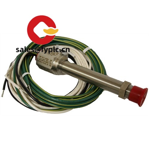
The 770085-1010-330 appears to be a factory-terminated, shielded cable assembly designed for control cabinets and motion systems—typically where a clean 10‑pin to 10‑pin connection is needed between sensors/encoders, I/O modules, or a drive and its feedback device. One thing I appreciate is the straightforward coding: “1010” generally indicates 10‑pin to 10‑pin, while “330” commonly denotes a 3.3 m length, which suits most panel-to-machine runs without excess slack. From my experience, this kind of assembly saves time on site, reduces wiring mistakes, and, in many cases, cuts down on electrical noise issues compared to field-terminated leads.
Our Order Placement Process and Guarantees
- Warranty: 365 days
- Delivery time: 1 week if in stock; no more than one month at the latest
- Payment: 50% advance payment, full payment before delivery
- Express options: FedEx, UPS, DHL
Key Features
- 10‑pin to 10‑pin, straight‑through wiring: Simplifies encoder, sensor, and I/O interconnects without pin mapping headaches.
- 3.3 m working length (typical): “330” suffix commonly indicates ~3.3 m, long enough for cabinet-to-machine routing but still tidy.
- Overall shielding: Helps suppress EMI in cabinets with VFDs and high-current lines; you might notice cleaner signals.
- Industrial jacket: Usually PVC or PUR depending on batch; resists oil and mechanical wear in most plant environments.
- Strain‑relieved connectors: Reduces conductor fatigue at terminations, especially in areas with vibration.
- Pre‑tested continuity: Assemblies are typically tested end‑to‑end to avoid on‑site troubleshooting and rework.
Technical Specifications
| Brand / Model |
AI‑TEK/ 770085-1010-330 |
| HS Code | 8544.42 (Fitted with connectors – insulated wire/cable) |
| Power Requirements | Not applicable (passive cable, no active electronics) |
| Length / Weight | Approx. 3.3 m length; weight typically < 0.6 kg depending on jacket |
| Operating Temperature | Typically −20 °C to +80 °C (varies with PVC/PUR jacket build) |
| Signal Input/Output Types | 10‑pin to 10‑pin, straight‑through; suited for sensor, I/O, and encoder/feedback signals |
| Communication Interfaces | Passive pass‑through (no protocol conversion; supports the host device’s signaling) |
| Shielding / Conductors | Overall shield; multi‑core conductors (gauge typically around 24 AWG) |
| Installation Method | Plug‑and‑play; route in cable duct/tray, connect to mating 10‑pin connectors, bond shield to earth as required |
Note: The “1010” and “330” interpretations are widely used conventions; please confirm pinout and length against your device manual before ordering.
Application Fields
- PLC and I/O cabinet wiring where a shielded multi‑pin harness is preferred
- Servo/drive feedback leads (incremental or absolute encoders) in motion axes
- General machine sensors and distributed I/O drops on assembly lines
- Packaging, printing, and robotics cells with moderate cable travel
Advantages & Value
- Reduced downtime: Pre‑terminated ends cut installation time and rework, especially during changeovers.
- Cleaner signals: Shielded design helps mitigate noise near VFDs and contactors.
- Broad compatibility: 10‑pin straight‑through works with many encoder and I/O headers (verify pinout and keying).
- Procurement simplicity: Stockable length, consistent labeling, and predictable lead times.
- Cost control: In many cases it’s more economical than custom field terminations and onsite testing.
Feedback from a maintenance supervisor last quarter: “We swapped in the 770085-1010-330 on a packaging line and the intermittent encoder fault disappeared. Seems the shielding and proper termination did the trick.”
Installation & Maintenance
- Environment: Route inside cabinet ducts or protected trays; avoid sharp edges and high‑temperature zones.
- Bend radius: Maintain a gentle bend (typically ≥10× cable OD) to protect shielding and conductors.
- Shield bonding: Terminate the shield at the designated end (drive or cabinet) per your EMC policy to prevent ground loops.
- Separation: Keep distance from high‑power motor leads; cross at 90° if paths must intersect.
- Checks: Verify continuity and pin‑to‑pin mapping with a tester before power‑up; tug‑test connectors for proper latch.
- Upkeep: Periodically inspect for abrasion, crushed spots, or loose strain relief; clean with lint‑free cloth, no solvents.
Quality & Certifications
- Materials typically compliant with RoHS
- CE marking is not usually applied to passive cables; conformity statements available on request
- UL/AWM styles may apply depending on jacket and conductor build; documentation provided per lot
- Manufacturer’s warranty support honored through our 365‑day warranty policy
Need a different length, jacket, or pinout? Share your device model and pin map; we’ll match a compatible variant before you place the order.


Reviews
There are no reviews yet.