
Description
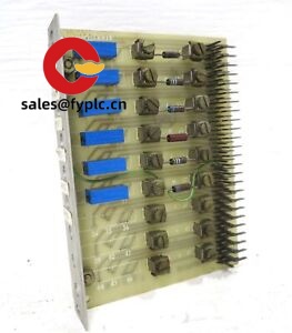
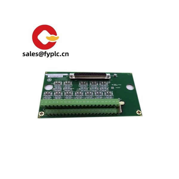
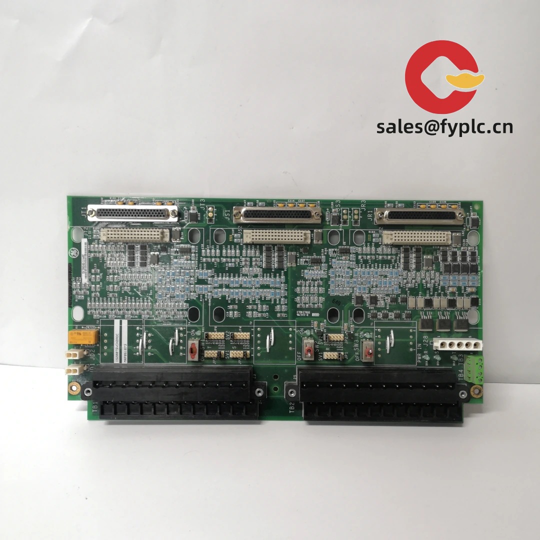
GE IC3600KMRA6D Relay Driver Board for Speedtronic Mark I/II Control Racks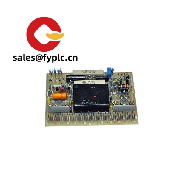
The GE IC3600KMRA6D is a relay driver/relay amplifier board used in early GE Speedtronic turbine control platforms (typically Mark I/II). From my experience, it sits in the IC3600 rack and translates logic-level control signals into robust relay drive outputs for trips, permissives, solenoids, and external interlocks. You might notice that plants choose this board when they need clean, reliable contact actuation without adding extra external interface hardware.
One thing I appreciate is its simplicity: discrete components, serviceable construction, and a stable design that has proven itself in hot, noisy cabinet environments. In many cases it’s a straight drop‑in swap for the same KMRA-series position, keeping downtime short and wiring untouched.
Company’s Order Placement Process and Guarantees
- Warranty: 365 days.
- Lead time: 1 week if in stock; no more than one month at the latest.
- Payment: 50% advance payment; full payment before delivery.
- Express options: FedEx, UPS, DHL.
- Process: Confirm part number and quantity → Issue PI → Receive advance payment → Functional check and packing → Ship with tracking → After‑sales follow‑up.
Key Features
- Purpose-built relay driving: Converts logic-level signals into reliable relay coil actuation for trips and permissives.
- Backplane integration: Plugs directly into the IC3600 rack; no external power wiring typically required.
- Noise immunity: Discrete design with snubbing and protection elements that help handle inductive loads in industrial cabinets.
- Drop-in replacement: Fits the standard GE IC3600 slot format, so changeout is fast during outages.
- Service-friendly layout: Through-hole components make troubleshooting and repair straightforward in many cases.
- Bench-tested before shipment: Each unit is electrically verified for core functions to reduce on-site surprises.
Technical Specifications
| Brand / Model | GE IC3600KMRA6D |
| System Compatibility | GE Speedtronic Mark I/II control racks (IC3600 series) |
| HS Code | 8538.90 (Parts for electrical control/switching apparatus) |
| Power Requirements | Backplane-supplied low-voltage DC via IC3600 rack; no separate external input |
| Dimensions & Weight | Single-slot IC3600 plug-in PCB; lightweight (< 0.5 kg typical) |
| Operating Temperature | Typically 0–60°C within a protected control cabinet; non-condensing |
| Signal I/O Types | Logic-level inputs from backplane; relay/coil drive outputs to external relays or interlock circuits |
| Communication Interfaces | None (non-serial, non-fieldbus; uses rack edge connector) |
| Installation Method | Plug-in card; mates with IC3600 edge connector; retained by rack hardware |
Related or Supporting Products
- GE IC3600KMRA6B / IC3600KMRA6C / IC3600KMRA7 variants: Closely related relay driver boards; selection depends on channel count and coil drive details. In many cases they are drop-in alternatives, subject to site wiring and logic mapping.
- GE IC3600 rack/backplane assemblies: Required host for KMRA-series cards; ensures correct power and edge-connector pinout.
- 24 VDC industrial relay packs (DIN-rail): Often used on the coil/load side for field isolation and contact multiplication; choose coil voltage/current to match KMRA drive capacity.
A maintenance supervisor in the Middle East told us this board “seems to be the least fussy part of the trip chain,” and they keep one spare on the shelf because swap and checkout typically takes under 30 minutes during planned outages.
Installation & Maintenance
- Cabinet environment: Install in a clean, ventilated control cabinet. Keep ambient 0–60°C, 5–95% RH non‑condensing. Avoid conductive dust and vibration where possible.
- Handling: Observe ESD precautions. Inspect the edge connector for oxidation; clean with approved contact cleaner if needed.
- Wiring & loading: Verify relay coil voltage/current and suppression (diodes or RC snubbers) per plant standards. Do not exceed channel drive ratings defined by the system documentation.
- Commissioning check: After insertion, run a logic test—energize/de‑energize each channel and confirm correct field relay response.
- Routine maintenance: Visual inspection every outage cycle; reseat connectors, check terminal tightness on the load side, and document any heat discoloration. No calibration typically required for this board type.
- Firmware: Not applicable (discrete hardware board with no firmware).
Quality & Certifications
- Quality checks: Visual and functional test prior to dispatch; packaging for shock and ESD protection.
- Certifications: Legacy GE hardware; CE/UL marking may depend on the complete installed system and era of manufacture. RoHS compliance is not guaranteed for older production.
- Warranty: 365-day replacement/repair warranty from shipment date.
- Traceability: Serial/part label recorded on the delivery note for maintenance records.


Reviews
There are no reviews yet.