
Description
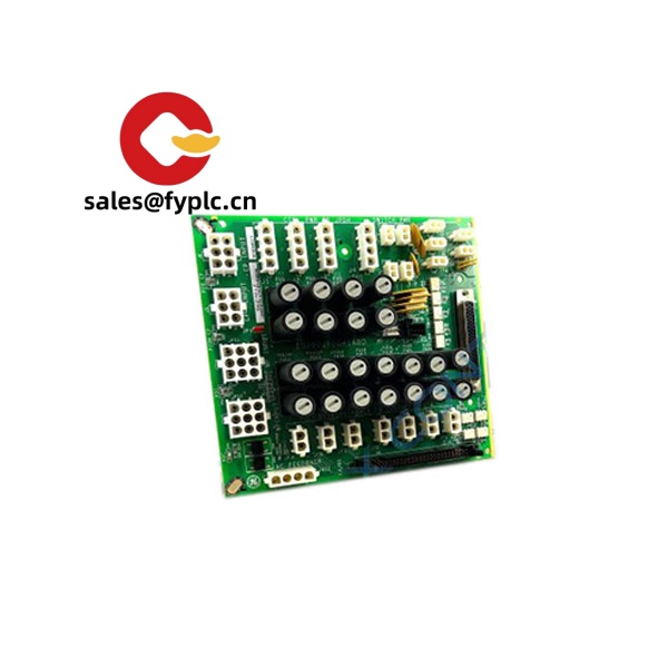
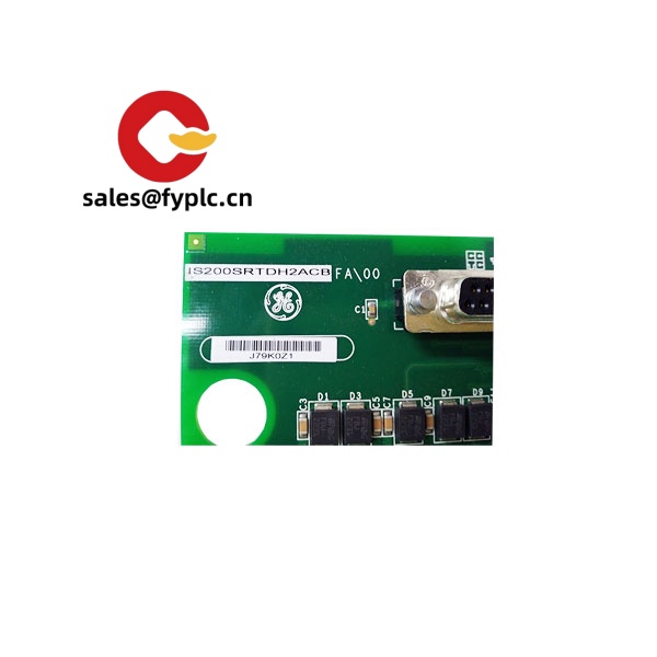
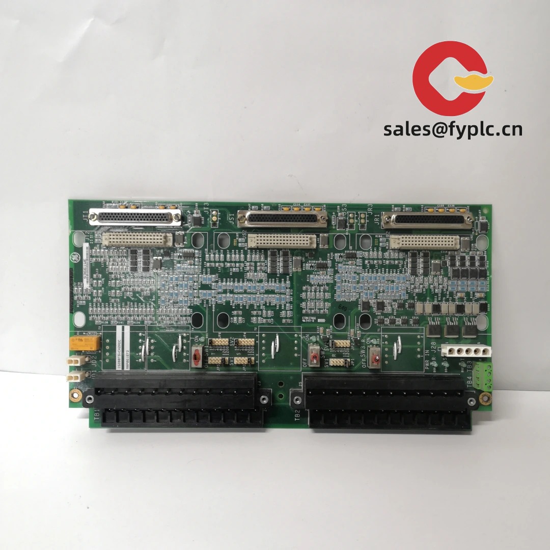
GE IS200SRTDH2A – RTD Terminal Board for Mark VI Temperature Inputs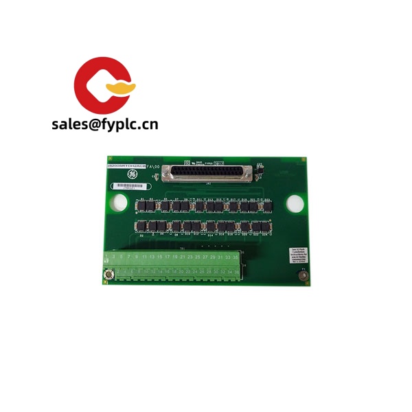
The GE IS200SRTDH2A is a small-format RTD terminal board used in Mark VI turbine and balance-of-plant controls. From my experience, it’s the go-to interface when you need reliable, multi-channel resistance temperature detector (RTD) wiring brought cleanly into the control system without fuss. The H2 variant typically supports dual-redundant I/O cabling, making it a solid choice for critical loops like lube oil, bearing metal, generator stator, or compressor casing temperatures where uptime matters.
Company’s Order Placement Process and Guarantees
-
- – Warranty period: 365 days
-
- – Delivery time: 1 week for in-stock items; no more than one month at the latest
-
- – Payment: 50% advance payment; full payment prior to delivery
-
- – Express options: FedEx, UPS, DHL
You might notice that we confirm electrical revisions before shipping. It reduces mismatch risk and, in many cases, saves a service visit later.
Key Features
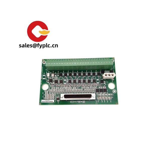
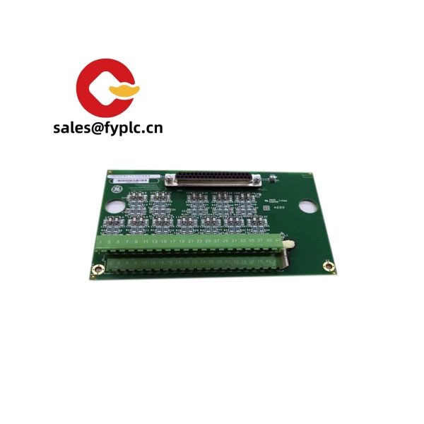
- Multi‑channel RTD termination – Barrier‑style terminals provide clean landings for field PT100/Ni/Cu RTDs, keeping cabinet wiring tidy.
- H2 redundant interface – Dual 37‑pin cable connectors typically support redundant I/O paths to the associated VRTD module(s), reducing single‑point failures.
- Passive board design – No local power required; excitation and measurement are handled by the VRTD input board, which helps with heat and reliability.
- Compatible RTD types – Designed for common 2‑ or 3‑wire RTDs used in industrial machines; actual type selection is made in the connected VRTD/Mark VI configuration.
- Noise‑sensitive routing – Short, shield‑friendly runs and differential measurement at the I/O board improve temperature signal stability in high‑EMI cabinets.
- Built for Mark VI – Form, fit, and wiring conventions align with GE Mark VI control panels, so retrofit effort is minimal in most cases.
Technical Specifications
| Brand / Model | GE IS200SRTDH2A |
| Product Type | RTD Terminal Board (Mark VI) |
| HS Code | 8538.90 (Parts suitable for electrical control equipment) |
| Power Requirements | None (passive); excitation and measurement provided by associated VRTD board |
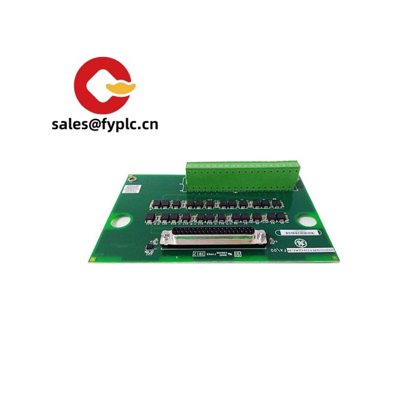
| Signal Input / Output | RTD sensor inputs (2‑ or 3‑wire); dual DC‑37 cable connectors to VRTD module(s) |
| Communication Interfaces | Not applicable (no on‑board communications) |
| Operating Temperature | 0 to 60 °C typical control cabinet environment |
| Installation Method | Panel / backplate mounting inside control cabinet; shielded cable routing recommended |
Related or Supporting Products
- IS200VRTDxx (e.g., IS200VRTDH1B / H2B) – RTD input boards that provide excitation and measurement; the SRTD board connects to these via DC‑37 cables.
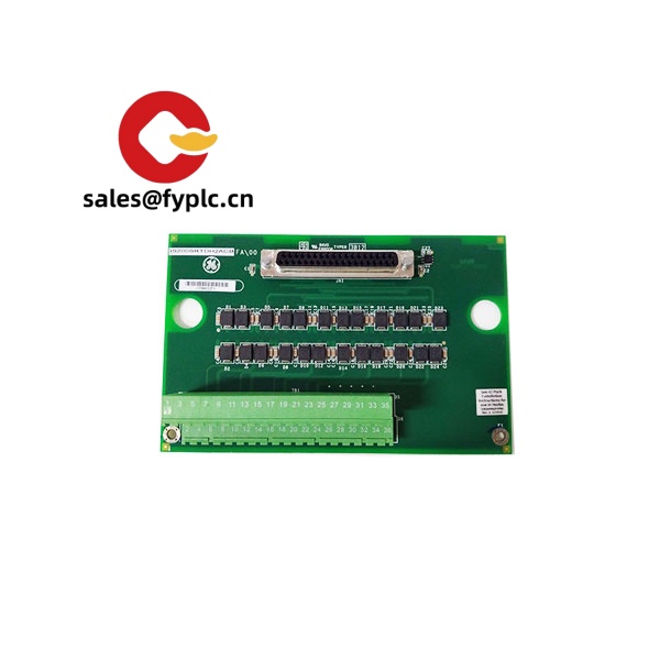
- IS200SRTDH1A – Similar terminal board, single‑path (H1) version for simplex systems.
- IS200TRTDH1B – Full‑size RTD terminal board variant, typically used when higher channel density or alternate terminal layout is preferred.
- GE shielded DC‑37 interface cables – Used to link terminal boards to the VRTD I/O boards; choose length based on cabinet layout.
One thing I appreciate is how the H2 path helps during maintenance. A maintenance lead at a combined-cycle site told us they could move a suspect channel to the alternate path in minutes and trend it, without a hot-swap on the spot.
Installation & Maintenance
- Cabinet environment – Keep the board in a clean, dry, ventilated enclosure; avoid mounting near VFDs or high‑EMI devices without proper segregation.
- Wiring practices – Use shielded twisted pairs for RTDs; land shields at one end (control side, typically) to minimize ground loops. Maintain consistent 2‑ or 3‑wire practices per channel.
- Grounding – Bond the cabinet ground properly; isolate sensor shields from field grounds unless your site standard dictates otherwise.
- Termination torque – Re‑check terminal screw torque after thermal cycling; loose terminations are a common cause of drift that “looks like” a bad probe.
- Routine checks – Visual inspection for discoloration, loose strands, or nicked insulation; clean dust with dry air. No calibration is required on the SRTD itself.
- Firmware/logic – Any updates apply to the connected VRTD or controller firmware, not this passive terminal board. Keep a record of I/O mapping before modifications.
- Safety – De‑energize and verify zero energy before touching field terminations; tag RTD circuits that feed trip logic to avoid unintended alarms.
Quality & Certifications
- CE conformity when installed as part of a compliant Mark VI system
- UL component recognition typically applicable to assemblies in this series
- Manufactured under ISO 9001 quality systems
- RoHS status may vary by build lot; later spares are often RoHS‑aligned
- Manufacturer’s warranty: 12 months (365 days)


Reviews
There are no reviews yet.