
Description
MTL 5541 Repeater Power Supply (2‑wire 4–20 mA/HART) – Slim, intrinsically safe isolator for DCS/PLC analog inputs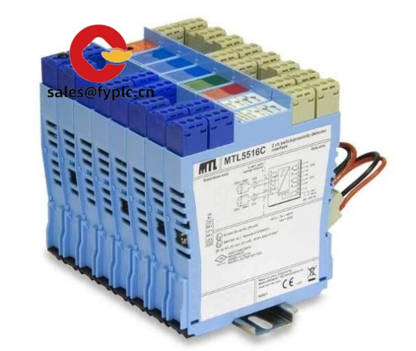
The MTL 5541 is part of the MTL5500 series of intrinsically safe galvanic isolators. It typically provides power to a 2‑wire transmitter in the hazardous area and repeats the 4–20 mA signal (with HART pass-through) to the safe area, where your DCS/PLC reads it cleanly. From my experience, it’s the go-to choice when you need reliable loop integrity, simple wiring on a 35 mm DIN rail, and rock-solid isolation that keeps noise and ground loops out of your measurement chain.
One thing I appreciate is how it behaves predictably across mixed plants: you power the MTL 5541 with a 24 VDC supply (typical), land your field transmitter on the hazardous side, and your control system sees a stable 4–20 mA signal with HART transparency. You might notice that commissioning becomes faster—loop checks are straightforward, and in many cases no special configuration tools are needed.
“We swapped a mix of older barriers for MTL 5541 modules on a brownfield upgrade. HART came through first time and the noise issues we used to see on long cable runs disappeared.” — Maintenance Lead, chemicals plant
Order Placement Process & Guarantees
- Warranty period: 365 days
- Delivery time: 1 week if in stock; no more than one month at the latest
- Payment: 50% advance payment; full payment prior to delivery
- Express options: FedEx, UPS, DHL
Key Features
- 2‑wire transmitter power with repeat output – Drives a hazardous‑area 2‑wire sensor and repeats a clean 4–20 mA signal to the safe area.
- HART transparent – Maintains HART communication to your host without additional hardware or special settings.
- Galvanic isolation – Three‑port isolation typically reduces ground loops and common‑mode noise in mixed earthing schemes.
- Slim DIN‑rail form factor – Compact module depth/width for dense cabinets; works with a power bus or point‑to‑point wiring.
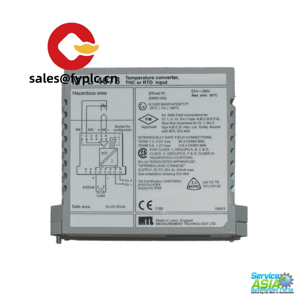
- Hazardous‑area interface – Designed for intrinsically safe loops between Zone 0/1 field devices and safe‑area control systems.
- Stable loop performance – From my experience, it handles long cable runs and typical field noise without drifting or chatter.
- Service‑friendly terminals – Clearly separated hazardous/safe terminals simplify loop checks and maintenance.
Technical Specifications
| Brand / Model | MTL 5541 (MTL5500 series) |
| Main Function | Repeater power supply for 2‑wire transmitters; 4–20 mA output with HART pass‑through |
| HS Code | 8543.70 (Other electrical machines and apparatus) |
| Power Requirements | 20–35 V DC (typical for MTL5500 modules) |
| Signal Input / Output | Hazardous area: powers a 2‑wire transmitter; Safe area: 4–20 mA analog output, HART transparent |
| Operating Temperature | -20 to +60 °C (typical) |
| Communication Interfaces | None; HART signal is passed through the analog loop |
| Isolation | Three‑port galvanic isolation (field / safe / power) |
| Installation Method | 35 mm DIN rail; individual supply wiring or power‑bus rail |
| Form Factor | Slim MTL5500 module (approx. 16 mm width) for high cabinet density |
Related or Supporting Products
- MTL 5541S – Same application space with a variant configuration; often selected when specific loop characteristics or compliance preferences apply.
- MTL 5544 – Multi‑channel/alternate channel density within the same series (useful when panel space is tight).
- MTL 5546 – Isolating driver/repeater options for different I/O types in the MTL5500 family.
- DIN‑rail power bus & end stops (MTL5500 accessories) – Clip‑on power distribution rail and end clamps to speed installation and reduce wiring.
- 24 VDC industrial power supply – Stable DC source sized for your module count and loop load.
- Alternative (compatibility check required): Pepperl+Fuchs KFD2/KCD2 transmitter supply modules—similar function; check channel count, approvals, and termination before substituting.
Installation & Maintenance
- Cabinet & environment – Mount on 35 mm DIN rail in a clean, ventilated enclosure. Keep ambient within -20…+60 °C (typical). Allow a little airflow space above/below the module.
- Wiring – Separate hazardous‑area and safe‑area terminations as labeled. Use twisted pair for analog loops; shield grounding at one end typically reduces noise. Maintain clear segregation per IS wiring practices.
- Earthing – Bond DIN rail and earth rail properly; maintain intrinsic safety barriers’ reference per the site earthing scheme.
- Power – 24 VDC supply is common; a power‑bus rail can simplify distribution if you have many modules.
- Commissioning – Verify polarity, loop continuity, and HART communication. A quick loop test at 4 mA and 20 mA usually confirms correct scaling.
- Maintenance – Routine visual inspection for terminal tightness and cleanliness. No firmware to update; periodic loop checks and cleaning of vent slots are usually sufficient.
- Safety – De‑energize before servicing. Ensure the hazardous‑area classification of the field device and wiring matches the isolator certification.
Quality & Certifications
- CE conformity; designed for use in intrinsically safe systems with typical ATEX/IECEx approvals (Ex ia) for suitable loops
- UL/cUL for industrial control equipment (region dependent)
- RoHS compliant components
- 365‑day warranty from us; extended coverage can be arranged case‑by‑case


Reviews
There are no reviews yet.