
Description
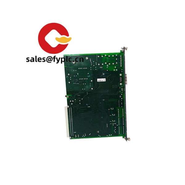
DEIF PCM4.4 – Modular power management module for reliable genset and paralleling control
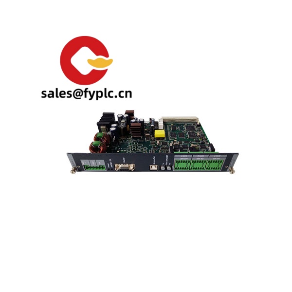
The DEIF PCM4.4 is a modular control module used in DEIF’s power management setups for generator sets, switchboards, and microgrid applications. From my experience, it sits well in projects where you want dependable synchronising, breaker control, and load sharing without overcomplicating the panel design. You might notice that it’s often chosen as a drop-in spare or expansion module in existing DEIF installations, making service work fast and predictable.
Typical use cases include: upgrading legacy gen-set panels to support busbar paralleling, adding extra I/O and protection to marine or offshore switchboards, and bolstering islanded microgrid control with stable load sharing. One thing I appreciate is how it usually integrates smoothly with DEIF ecosystems and standard SCADA via Modbus, so commissioning tends to be straightforward in most cases.
Order Placement Process and Guarantees
- Warranty: 365 days
- Delivery time: 1 week for in‑stock; no more than one month at the latest
- Payment: 50% advance payment, full payment before delivery
- Express delivery: FedEx, UPS, DHL
Key Features
- Paralleling & load sharing – Supports generator-to-generator and generator-to-mains coordination for stable power flow and balanced kW/kVAR sharing.
- Synchronising and breaker control – Handles synchronisation checks and trip/close sequencing to reduce switching stress and speed up transfer.
- Configurable I/O – Typically provides a mix of digital inputs, relay outputs, and analog channels (0–10 V / 4–20 mA) for protection, interlocks, and PLC/AVR interfaces.
- SCADA-friendly communications – Commonly supports Modbus RTU over RS‑485; CAN-based load-share is often available in DEIF systems.
- Stable island and grid operation – Works in islanded, mains-parallel, or shore-parallel modes where smooth transitions matter.
- Rugged design for switchboards – Built for industrial environments; typically 24 VDC supply and wide operating temperature to handle real-world panels.
- Service-friendly – Firmware updatable and parameter-driven setup helps reduce site time during commissioning or replacements.
Technical Specifications
| Brand / Model | DEIF PCM4.4 |
| HS Code | Typically 8537.10 (boards/panels for electric control, ≤1000 V); final classification can vary by configuration and country |
| Power Requirements | 24 VDC nominal (commonly 8–36 VDC tolerated in DEIF control platforms) |
| Operating Temperature | Typically −20 to +70 °C (application dependent) |
| Signal Input/Output Types | Digital inputs (dry contact), relay outputs, analog inputs/outputs (0–10 V / 4–20 mA), suitable for AVR/governor interfacing |
| Communication Interfaces | RS‑485 (Modbus RTU) commonly used; CAN for load-share in DEIF systems; Ethernet options may be available via companion units |
| Installation Method | Switchboard installation on 35 mm DIN rail or backplate inside a ventilated cabinet |
Related or Supporting Products
- DEIF AGC-4 – Advanced genset controller with integrated HMI; ideal if you want full front‑panel operation and expanded feature sets.
- DEIF AGC-150 – Compact controller for single units and simple paralleled systems; more cost-effective in smaller projects.
- DEIF PPM 300 – Power management platform for complex multi‑bus systems and marine switchboards.
- DEIF ASC-4 – Automatic synchroniser; a clean choice when you primarily need reliable sync and breaker control.
- DEIF LS-6 – Line surveillance module; adds dependable line/bus monitoring and interlocking.
A maintenance supervisor recently shared that swapping a legacy synchroniser for a PCM‑series module cut their changeover time by half, mainly because the I/O mapping and Modbus tags lined up with their existing SCADA. That seems to be a recurring pattern with DEIF gear.
Installation & Maintenance
- Panel/cabinet – Install in a clean, dry switchboard with IP-rated enclosure. Allow airflow; avoid heat sources and high‑EMI zones.
- Power & grounding – Use a stable 24 VDC supply with proper grounding. Isolate supplies for I/O where needed to reduce noise.
- Wiring practices – Separate signal and power cables. Use twisted pair/shielded lines for RS‑485 and CAN. Terminate bus ends correctly.
- Protection & interlocks – Verify breaker coil ratings and interlock logic before energising. Confirm sync checks and protections in test mode.
- Routine maintenance – Inspect terminals quarterly, clean dust from the cabinet, back up parameters after any change, and keep firmware at a validated revision.
- Commissioning tips – Validate CT/PT ratios, frequency/voltage windows, and droop/isochronous settings under supervised load tests.
Quality & Certifications
- Manufacturer quality system typically ISO 9001
- CE and RoHS conformity for industrial use
- UL/cUL and selected marine approvals (e.g., DNV‑GL, ABS) may be available depending on variant
- Standard manufacturer’s warranty: 1 year (365 days)
If you’re replacing an existing PCM‑series module, sharing a photo of the nameplate and your I/O list typically helps confirm compatibility and lead time. We can align firmware and parameters so it lands on site ready to wire.


Reviews
There are no reviews yet.