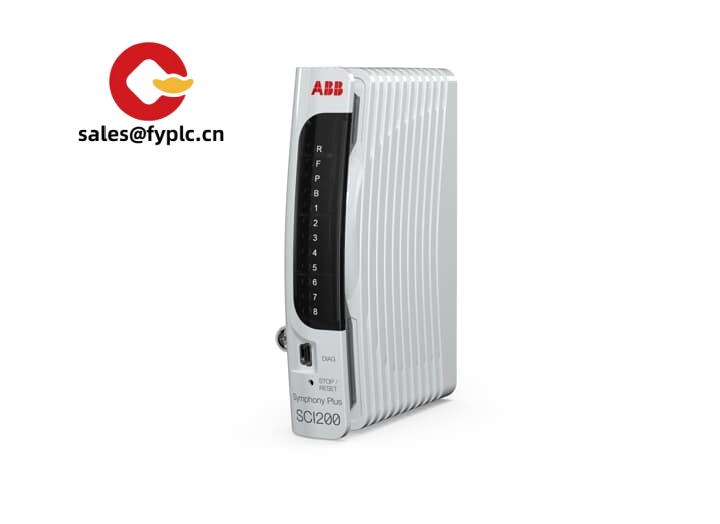

Description
SCM040 4‑Channel Signal Conditioning Module for 0–10 V / 4–20 mA Loops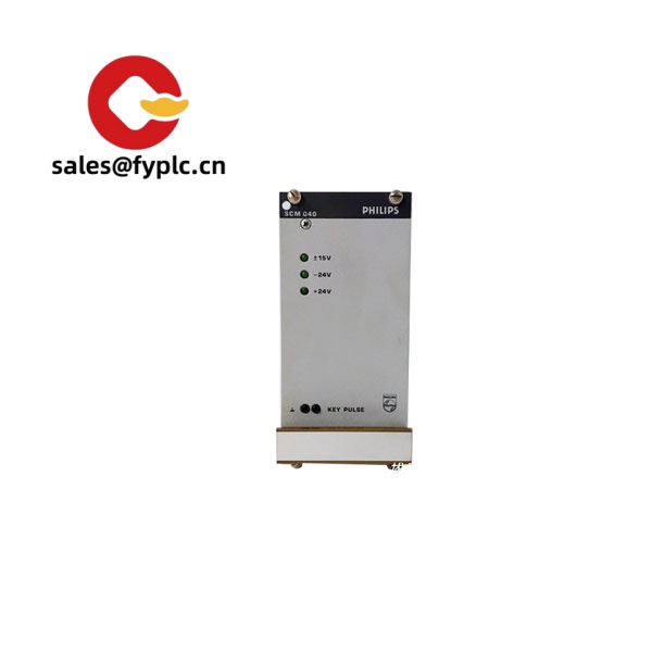
The SCM040 is a compact, DIN‑rail signal conditioning module designed to isolate, convert, and stabilize analog process signals across four independent channels. From my experience, it’s the kind of “fit-and-forget” hardware you drop into a control cabinet when you need clean, reliable analog I/O without adding another PLC rack. You might notice that it reduces ground loops and noise pickup immediately, especially in mixed 24 VDC and AC drive panels.
Typical use cases include: splitting and isolating 4–20 mA transmitter loops to multiple controllers, converting 0–10 V sensors to current loops for long cable runs, or protecting PLC analog cards from field-side surges. A maintenance supervisor told me, “We swapped two unstable pressure loops onto SCM040 channels and the drift basically disappeared,” which sums up its purpose pretty well.
Our Order Placement Process and Guarantees
- Warranty: 365 days
- Delivery time: 1 week if in stock; no more than one month at the latest
- Payment: 50% advance payment; full payment prior to delivery
- Express delivery options: FedEx, UPS, DHL
Key Features
- Four isolated analog channels – Each channel operates independently, ideal for mixed sensor types in one cabinet.
- 0–10 V and 4–20 mA support – Selectable per channel to match common field transmitters and drives.
- 3‑way galvanic isolation – Input/Output/Power isolation typically up to 2.5 kVrms helps break ground loops and improves EMC immunity.
- Fast, stable conversion – Low ripple and quick response (in many cases within milliseconds) for tight loop performance.
- 24 VDC cabinet ready – Runs from standard 24 VDC control power with low consumption.
- DIN‑rail 22.5 mm slim body – Saves space and leaves room for service loops and ducting.
- Front DIP selection – Simple, tool‑light configuration; techs typically set it once and move on.
- Status LEDs per channel – Quick visual check for power and signal presence during commissioning.
- High accuracy and low drift – Keeps analog values aligned with PLC scaling for cleaner trends and fewer alarms.
Technical Specifications
| Brand / Model | SCM040 (Signal Conditioning Module) |
| HS Code | 8543.70 (Electrical machines and apparatus, having individual functions) |
| Power Requirements | 24 VDC nominal (18–30 VDC), < 3 W typical |
| Dimensions & Weight | Approx. 114.5 × 99 × 22.5 mm; ~150 g (DIN‑rail form factor) |
| Operating Temperature | −20 to +60 °C; 5–95% RH, non‑condensing (typical for this class) |
| Signal I/O Types | 4× analog inputs (0–10 V or 4–20 mA selectable), 4× isolated analog outputs (repeater/conditioned pass‑through) |
| Accuracy / Response | ±0.1% FSR typical; response ≤ 10 ms (10–90%), low ripple |
| Isolation | 3‑way isolation (Input/Output/Power), up to 2.5 kVrms, 60 s test (typical) |
| Communication Interfaces | None (analog signal conditioning; no fieldbus required) |
| Installation Method | DIN‑rail (EN 60715), pluggable screw terminals 0.2–2.5 mm² |
Related or Supporting Products
- SCM020 – 2‑channel variant for smaller panels; same isolation concept with half the footprint.
- SCM080 – 8‑channel model when you want higher density per rail segment.
- SCM040‑H – Version with HART‑transparent current loops, useful if asset management systems are in play.
- LPS24‑1.0A – 24 VDC DIN‑rail power supply sized for low‑power signal modules.
- SPD24 – 24 V surge protection for analog lines in noisy or outdoor runs.
Installation & Maintenance
- Cabinet & mounting – Install on a 35 mm DIN‑rail inside an IEC cabinet. Keep at least 25–50 mm clearance above/below for airflow. Avoid mounting directly beside VFDs without a divider.
- Wiring – Use shielded twisted pairs for analog signals; land shields to a single‑point earth. Separate high‑voltage or motor cables from analog lines by 100 mm or more where possible.
- Power – Feed from a clean 24 VDC supply with proper grounding. In many cases, a small dedicated PSU reduces noise coupling.
- Configuration – Set each channel (voltage or current) via front DIP switches. Verify scaling with a portable calibrator before handing off to operations.
- Safety – De‑energize before wiring. Observe ESD precautions when handling. Confirm loop polarity to avoid inadvertent sensor shutdown.
- Routine checks – Annual spot‑calibration is typically enough. Light dusting with dry air, inspect terminal torque, and confirm LED status during PM rounds.
Quality & Certifications
- CE marking and RoHS compliance are standard for this class of module; UL/cUL recognition is commonly available on production variants.
- Manufactured under ISO 9001 quality systems (typical for reputable OEMs in this segment).
- Warranty: 365 days from shipment.


Reviews
There are no reviews yet.