
Description
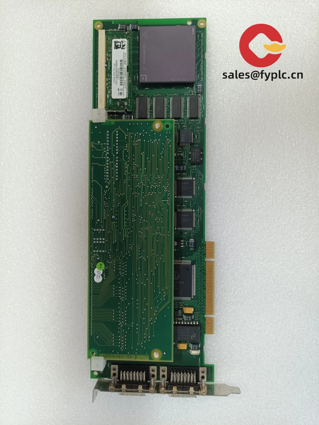
ABB SDCS-PIN-11 – Pulse Interface Board for DCS500/DCS600 DC Drives
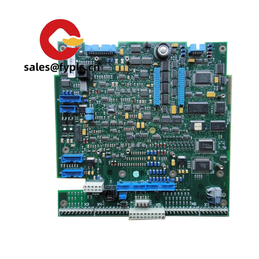
The ABB SDCS-PIN-11 is the pulse interface board commonly used in DCS500/DCS600 DC drive systems to generate and condition firing pulses for the thyristor bridge. From my experience, this board is the piece that quietly keeps rectifier firing angle rock-solid, so the drive maintains stable torque and speed even when line conditions aren’t perfect. If you’re maintaining legacy ABB DC lines, the SDCS-PIN-11 is typically a drop-in replacement, keeping downtime short and commissioning straightforward.
Order Placement Process and Guarantees
- Warranty: 365 days
- Delivery: 1 week for in-stock; no more than one month at the latest
- Payment: 50% advance payment, full payment before delivery
- Express options: FedEx, UPS, DHL
- Verification support: Pictures and functional reports can be provided prior to shipment upon request
Key Features
- Dedicated thyristor firing interface – Generates and conditions gate pulses for the rectifier bridge used in ABB DCS500/DCS600 DC drives.
- Stable synchronization – Phase-locked firing timing helps maintain smooth torque and speed, even with minor mains fluctuations.
- Robust isolation – Output stages are typically optically or transformer-isolated to reduce noise coupling into the control electronics.
- Internal backplane integration – Works with SDCS control/power boards; no fieldbus setup needed for replacement.
- Diagnostics-friendly – Status indications and acknowledgement of pulses (where supported) simplify troubleshooting during service calls.
- Serviceable spare – In many cases, it’s a direct swap with minimal parameter changes, keeping restart times short.
Technical Specifications
| Brand / Model | ABB SDCS-PIN-11 |
| Primary Function | Pulse interface (firing) board for thyristor bridge control in DCS500/DCS600 DC drives |
| HS Code | 8504.90 (Parts of static converters) |
| Power Requirements | Backplane supplied, typically from the drive’s low-voltage supply (via SDCS-POW) |
| Operating Temperature | Typically 0…+55°C when installed in the standard ABB drive cabinet environment |
| Signal I/O Types | Thyristor gate trigger outputs; line phase reference inputs; status/acknowledge signals with galvanic isolation |
| Communication Interfaces | Internal SDCS backplane; no external fieldbus on the board itself |
| Installation Method | Plug-in PCB module inside the DCS500/DCS600 rack with card guides and fixed connectors |
Related or Supporting Products
- ABB SDCS-CON-2A – Main control board that handles regulation loops and communicates with I/O; the PIN board follows its firing commands.
- ABB SDCS-POW-1 – Power supply board providing low-voltage rails to control PCBs, including the SDCS-PIN series.
- ABB SDCS-IOB-2 – Digital/analog I/O expansion for field signals; often present in DCS500/DCS600 cabinets.
- ABB SDCS-PIN-48 / SDCS-PIN-51 – Alternative pulse interface variants used with different bridge configurations or current ranges; selection depends on drive frame and rectifier setup.
If you’re replacing SDCS-PIN-11, it’s worth checking the drive type code and rectifier configuration (6‑pulse vs. 12‑pulse) to confirm the exact board variant. You might notice that older cabinets sometimes mix revisions; we can help cross-check before shipping.
Installation & Maintenance
- Cabinet environment – Install only in the designated SDCS rack inside a ventilated cabinet. Keep ambient within the drive’s rated temperature and humidity.
- Wiring & grounding – Maintain proper PE bonding and shield terminations. Gate/trigger connections must follow ABB’s wiring diagram for your bridge type.
- Phase reference – Verify correct phase rotation and synchronization signals after installation; mis-phased references can lead to misfiring.
- ESD handling – Treat the board as ESD-sensitive. Use grounded wrist straps and handle by edges only.
- Routine care – Periodically clean dust from the cabinet and card guides; check connectors for oxidation. No regular calibration is typically required for this board.
- Firmware/parameters – The PIN board itself doesn’t usually require firmware updates. After replacement, confirm drive parameters and run a low-load test run.
One thing I appreciate is how quickly these boards can be swapped. In many cases, technicians report a 30–45 minute changeover including basic checks, assuming spare access and cabinet documentation are on hand.
Quality & Certifications
- CE – Conformity applies at the drive assembly level; the SDCS-PIN-11 is a service part for CE-marked ABB drives.
- UL/cUL – Typically recognized when installed within the certified DCS500/DCS600 drive.
- ISO – Manufactured under ABB’s ISO 9001 quality system.
- Warranty – 365 days coverage from delivery date.


Reviews
There are no reviews yet.