
Description
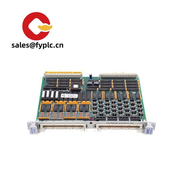
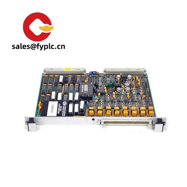
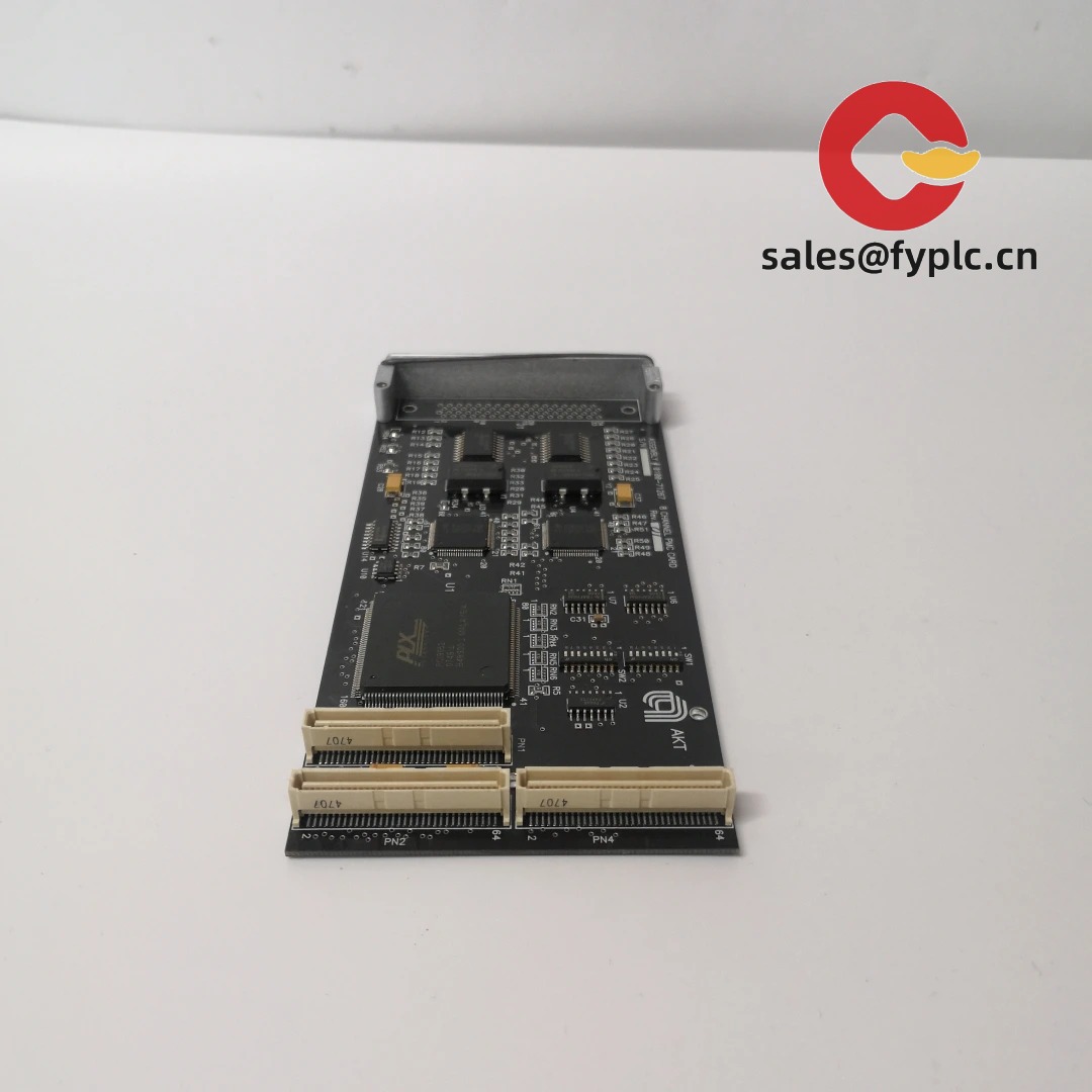
VMIC VMIVME-3115 – Multi‑Channel Analog Input Board for VME Data Acquisition and Plant Control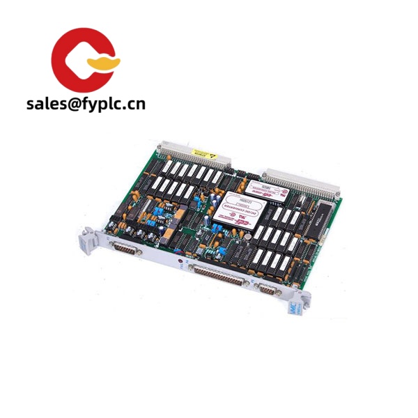
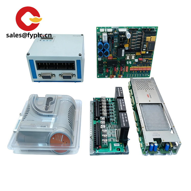
The VMIC VMIVME-3115 is a legacy VMEbus analog input module designed for reliable, high-density data acquisition. From my experience, it’s typically used in turbine monitoring, power generation DCS upgrades, hardware‑in‑the‑loop test stands, and retrofit projects where stable, long‑term support matters more than flashy specs. You might notice that it combines a multiplexed analog front end with a robust VME interface, so it drops neatly into a 6U VME chassis and starts streaming conditioned analog data to your real‑time controller without drama.
One thing I appreciate is how forgiving it is in mixed-signal cabinets: shielded wiring, a grounded backplane, and modest airflow are usually all it needs. If you’re replacing older VMIC AI boards or consolidating multiple slow channels into one slot, the VMIVME-3115 tends to be a safe, low‑risk option.
Order Placement Process and Guarantees
- Warranty: 365 days
- Lead time: 1 week when in stock; no more than 1 month at the latest
- Payment: 50% advance payment; full payment prior to delivery
- Express options: FedEx, UPS, DHL
Key Features
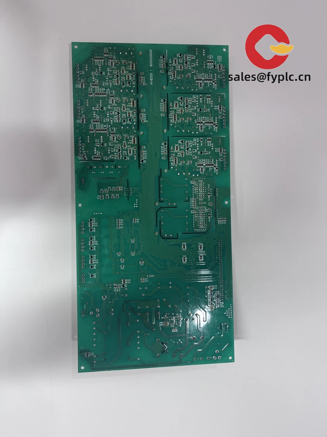
- VMEbus integration – Standard 6U VME board that fits common 19-inch VME chassis; straightforward addressing and interrupt support.
- Multiplexed analog inputs – Built for multi‑channel voltage acquisition; ideal for slow to moderate scan rates across many points.
- Programmable input ranges – Supports typical industrial ranges for clean scaling in your control software.
- Flexible triggering – Software‑controlled scanning with optional external trigger/interrupt lines, useful for synchronized captures.
- Calibration-friendly – Onboard gain/offset trims and test points make field calibration easier during scheduled outages.
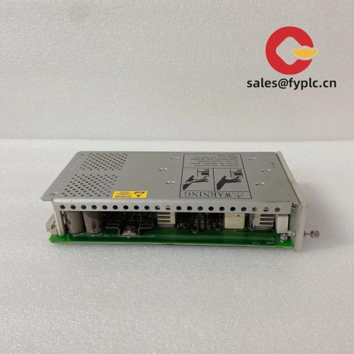
- Rugged for plant floors – Stable operation in standard commercial temperature ranges; handles electrical noise well when wired properly.
- Long lifecycle support – Well-known VMIC design that remains serviceable in many installed VME systems.
Technical Specifications
| Item | Specification |
| Brand / Model | VMIC VMIVME-3115 |
| Product Type | VMEbus analog input (A/D) module, multiplexed channels |
| HS Code | 847330 (commonly declared for printed circuit assemblies; confirm locally) |
| Power Requirements | VME backplane power; typically +5 V and ±12 V rails (consumption depends on configuration) |
| Dimensions & Weight | 6U VME (approx. 233.35 mm × 160 mm); ~0.6–0.8 kg typical |
| Operating Temperature | 0 to +55 °C (commercial); storage typically −40 to +85 °C |
| Signal Input/Output Types | Analog voltage inputs (multiplexed); optional external trigger/interrupt line support |
| Communication Interfaces | Standard VMEbus interface for data, control, and interrupts |
| Installation Method | 6U VME slot mounting; front‑panel high‑density connectors to field wiring or breakout panels |
Related or Supporting Products
- VMIVME-3113 / VMIVME-3114 – Similar multiplexed analog input boards; often chosen when channel count or scan behavior needs to match older installations.
- VMIVME-3122 / VMIVME-3128 – Higher‑performance analog input options (simultaneous or higher‑resolution variants, depending on model family).
- VMIVME-412X series – Complementary analog output (D/A) boards for closed‑loop control or stimulus generation.
- 6U VME Chassis & PSU – 19″ rack chassis with adequate +5 V and ±12 V capacity; choose airflow front‑to‑rear for denser systems.
- Shielded Breakout Panel (IO-BREAKOUT-68) – Panel‑mount screw terminal breakout for high‑density AI connectors; simplifies field wiring and shielding.
- Shielded Cable (SHIELDED-CABLE-68‑2M) – 2 m shielded high‑density cable from board front panel to breakout; strain‑relief recommended in mobile racks.
Quick customer note: a maintenance team in a combined‑cycle plant swapped to a VMIVME‑3115 during a 6‑hour outage, kept the original pinout via a breakout panel, and had their historian logging again in under an hour of I/O checks—no software changes beyond range scaling.
Installation & Maintenance
- Cabinet & chassis – Use a 6U VME chassis with clean backplane power. Maintain front‑to‑rear airflow; leave at least 1U clearance for cabling if possible.
- Wiring practices – Use shielded twisted pairs for analog lines; ground shields at the cabinet side only in most cases. Keep AI wiring separated from high‑energy circuits.
- Range & scaling – Match input ranges to your sensors or signal conditioners; verify scaling in your RTOS or SCADA before going live.
- Grounding – Bond chassis ground to plant ground; avoid ground loops by using differential inputs for long runs or noisy environments.
- Calibration – Schedule annual calibration checks. The board provides gain/offset trims; document as‑found/as‑left values for audit trails.
- Cleaning – Every 6–12 months, power down and remove dust with dry, oil‑free air; inspect connectors for oxidation and re‑seat if needed.
- Firmware/EPROM – Legacy boards may carry PLD/EPROM revisions; in most cases you’ll keep the existing version to maintain compatibility, but verify during system FAT.
- Spares strategy – For 24/7 plants, keeping one spare on the shelf typically reduces MTTR significantly during unplanned outages.
Quality & Certifications
- Certifications – CE compliance and ISO 9001 manufacturing processes are typical for this product family; UL/CSA usage is common in VME systems. RoHS status may vary due to legacy design.
- Warranty – 365‑day warranty provided by us. Manufacturer’s original warranty may no longer apply on legacy units.
- Traceability – We can provide test reports or functional verification results upon request for critical applications.


Reviews
There are no reviews yet.