
Description
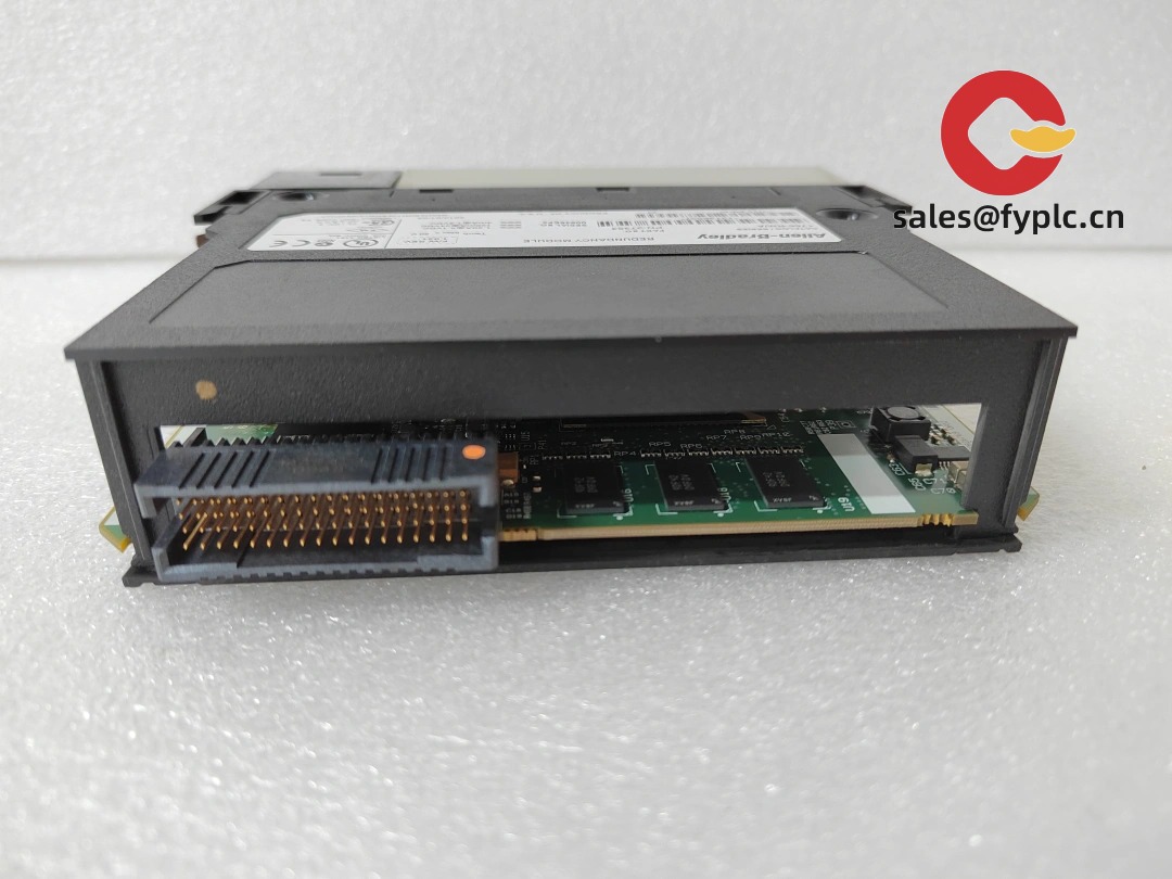
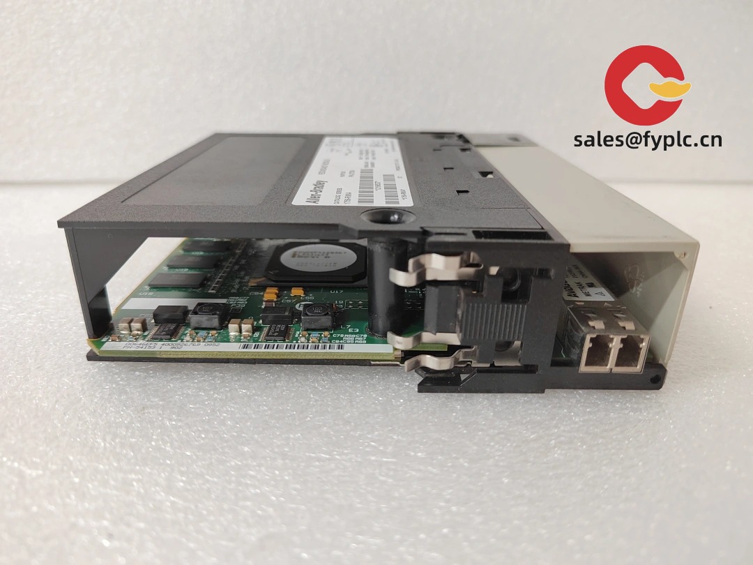
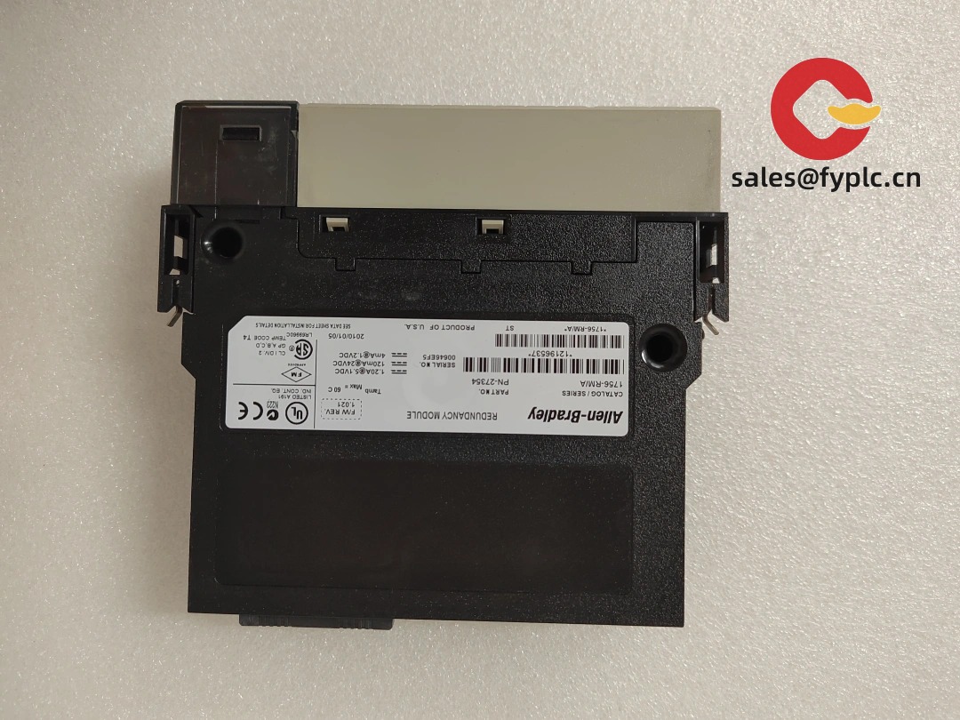
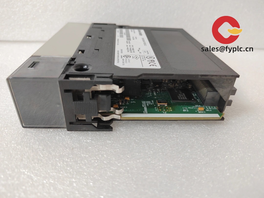
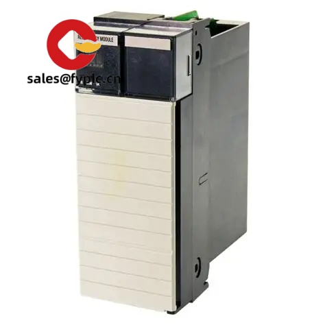
Allen‑Bradley 1756‑RM_A – ControlLogix Redundancy Module (Series A) for Primary/Standby CPU Systems
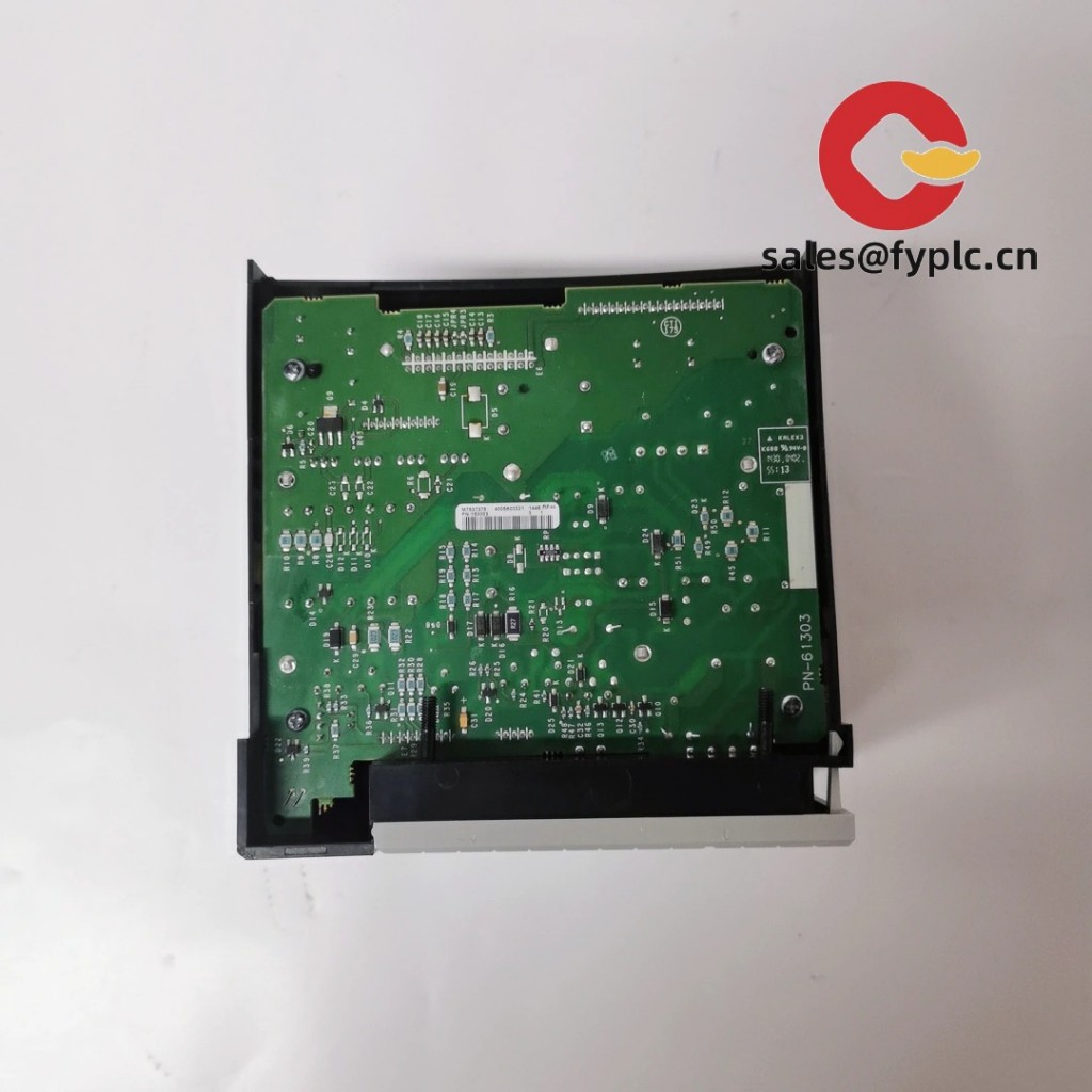
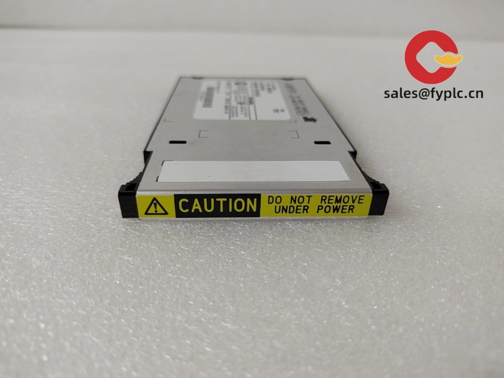
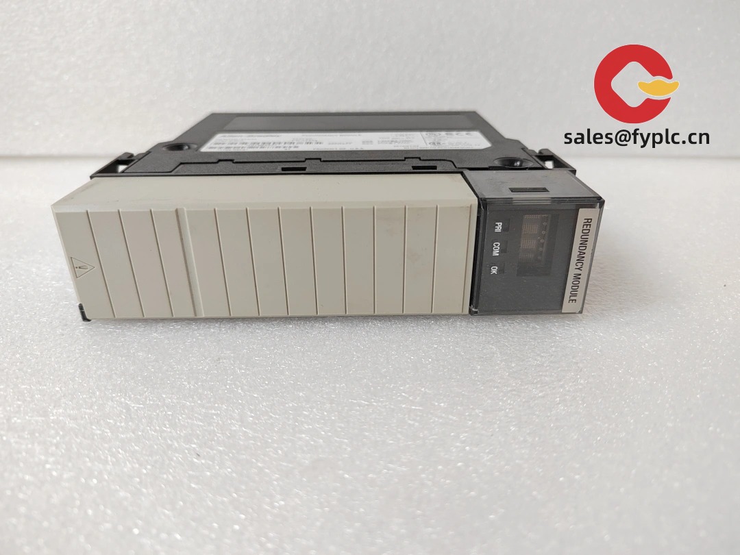
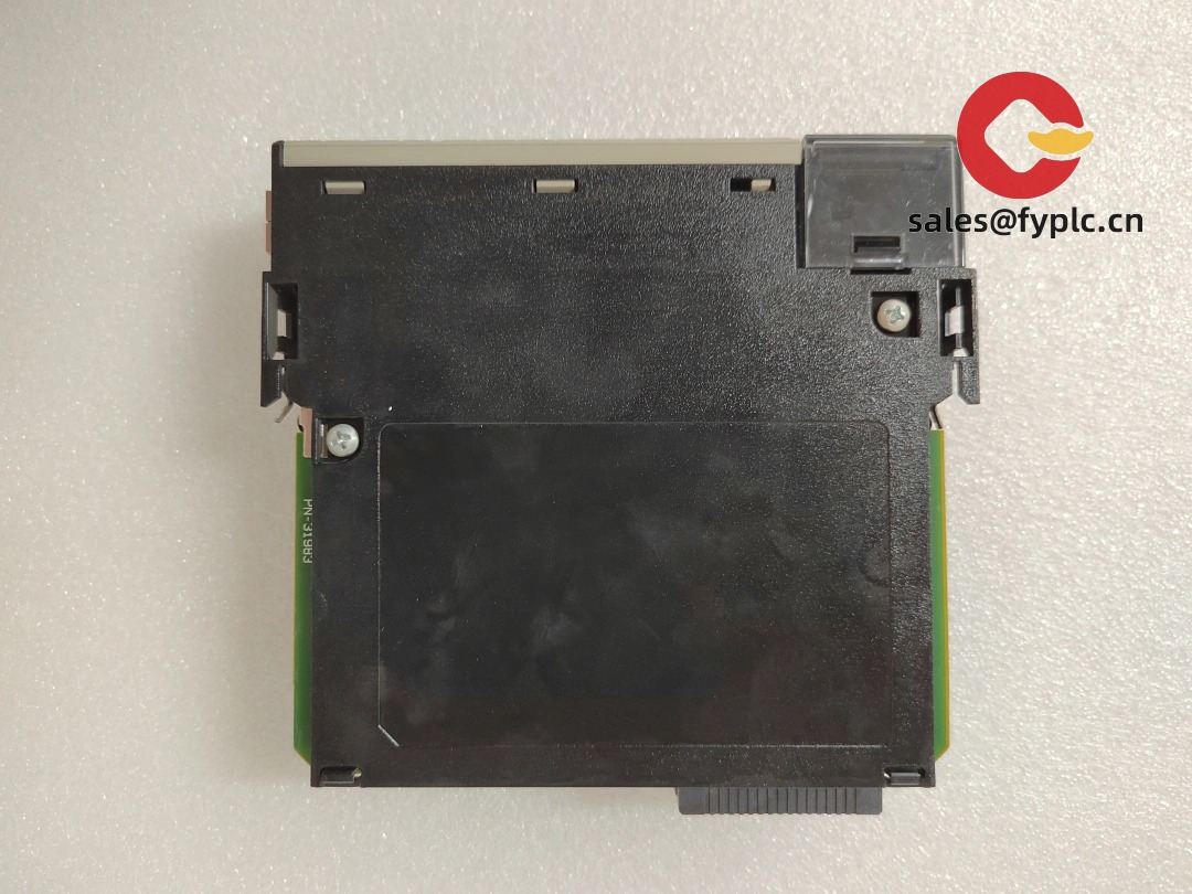
The Allen‑Bradley 1756‑RM_A is the redundancy module used to pair two ControlLogix racks into a primary/standby system. In practice, it synchronizes the controller state over a dedicated redundancy link so the standby chassis can take over automatically if the primary drops. From my experience, it’s the most straightforward way to add high availability to an existing 1756 architecture—mirror the slot layout, cable the RM link, align firmware, and you get predictable switchover behavior with clear diagnostics.
Company’s Order Placement Process and Guarantees
- Warranty: 365 days
- Delivery time: 1 week for in‑stock; no more than one month at the latest
- Payment: 50% advance payment, full payment for delivery
- Express delivery methods: FedEx, UPS, DHL
- Pre‑shipment checks: visual/label verification and port integrity; ESD‑safe, shock‑resistant packing
Key Features
- Primary/standby control – Mirrors controller state so the standby rack can assume control automatically on a fault.
- Dedicated redundancy link – Uses a point‑to‑point RM cable (1756‑RMCx length options) between matched slots for stable, deterministic sync.
- Backplane integration – Bridges redundancy services to the 1756 backplane; no rework of field I/O wiring.
- Clear diagnostics – Front LEDs and status states (Primary/Secondary/Sync) make health checks quick during maintenance windows.
- Brownfield‑friendly – Fits a standard single‑slot; typically only requires matched chassis layout and firmware alignment.
Technical Specifications
| Brand / Model | Allen‑Bradley 1756‑RM_A (Series A) |
| Function | ControlLogix redundancy module for primary/standby CPU systems |
| Redundancy Link | Point‑to‑point cable between paired modules (1756‑RMCx lengths; site‑dependent) |
| HS Code (reference) | 8538.90 – Parts suitable for electrical control equipment |
| Power Requirements | Powered via 1756 backplane (no external supply on the module) |
| Communication Interfaces | Redundancy link port (to mate 1756‑RM); backplane interface to controller |
| Operating Temperature | Typically 0…+60 °C (enclosure‑installed; non‑condensing) |
| Dimensions & Weight (approx.) | Standard 1756 single‑slot module; ~0.3–0.5 kg |
| Installation Method | Install one 1756‑RM per chassis in the same slot; connect redundancy cable; match chassis slot layout |
Application Fields
I typically see the 1756‑RM_A in plants where uptime is non‑negotiable and the 1756 base should be preserved:
- Power & utilities – redundant controller pairs for boiler/BOP islands.
- Oil & gas / petrochem – E&I cabinets where a switchover must be controlled and quick.
- Water & wastewater – process PLCs that must ride through planned CPU maintenance.
- F&B and life sciences – validated systems that benefit from mirrored racks and minimal change control.
A controls engineer summed it up nicely: “We mirrored the slot layout, cabled the RM link, ran a forced switchover, and the process held steady.” That’s been the typical outcome when firmware and hardware revisions are lined up.
Advantages & Value
- Reliability – Automatic primary/standby switchover helps keep loops alive through CPU faults or maintenance.
- Compatibility – Native to ControlLogix; preserves existing I/O, wiring, and module choices.
- Cost control – Adds high availability without migrating platform or redesigning cabinets.
- Maintainability – Clear status states and predictable procedures shorten outage windows.
- Support – We can help verify slot alignment, cable length (RMC1/3/10), and firmware targets before shutdown.
Installation & Maintenance
- Rack pairing: Use two 1756 chassis with identical slot layouts; install the 1756‑RM in the same slot in each rack.
- Redundancy cable: Connect the RM‑to‑RM link with an approved 1756‑RMCx cable; route away from high‑noise conductors.
- Firmware & modules: Align controller and module firmware across both racks; keep catalog numbers/series matched where required.
- Switchover test: During commissioning, perform a controlled failover (stop primary CPU or pull primary power) to verify system behavior.
- Grounding/EMC: Bond both enclosures properly; maintain shield continuity; keep the link cable strain‑relieved.
- Routine care: Periodic dust cleaning, connector re‑torque, and a quick review of redundancy health/diagnostics.
Quality & Certifications
- Manufactured under Rockwell Automation quality systems (ISO 9001 aligned).
- CE/UL/cUL markings apply at the system/module level per Rockwell documentation.
- RoHS status depends on series/lot; confirmable by part/serial if needed.
- Warranty: 365 days repair/replace coverage from delivery.


Reviews
There are no reviews yet.