
Description
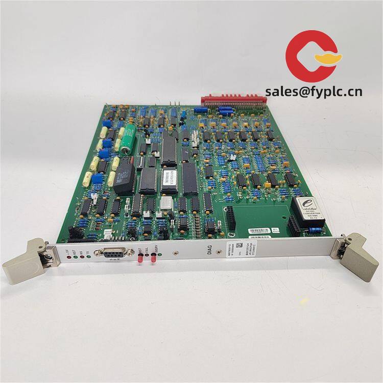
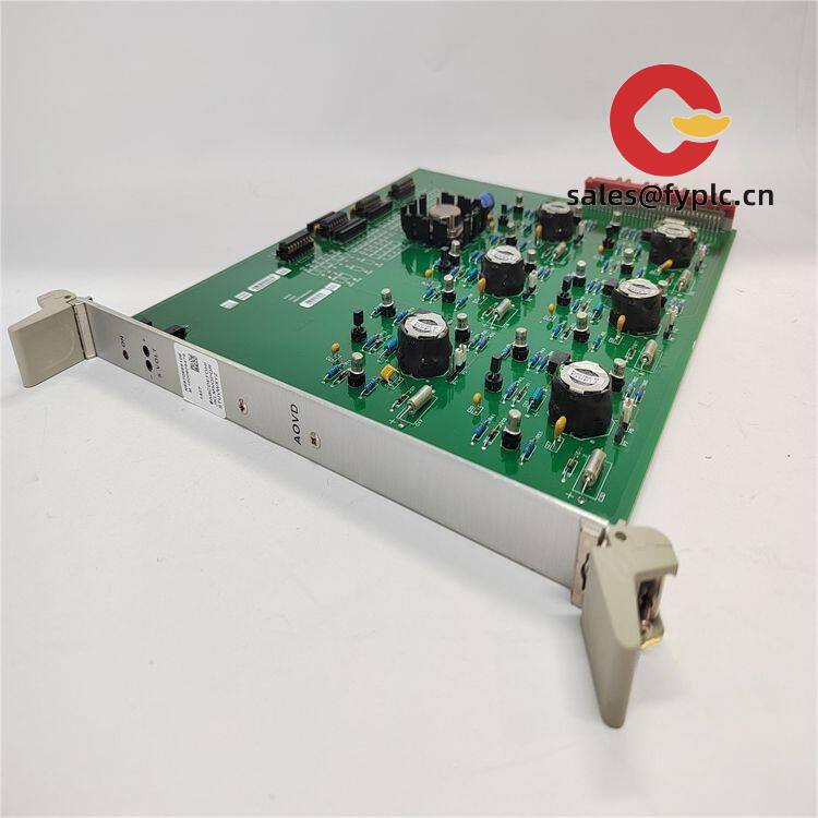
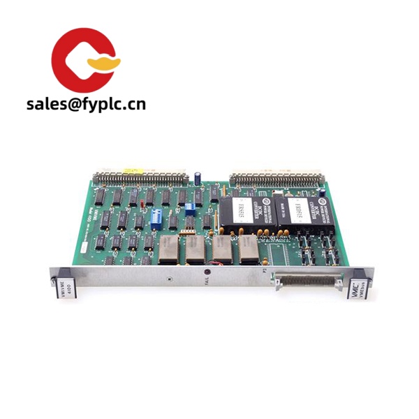
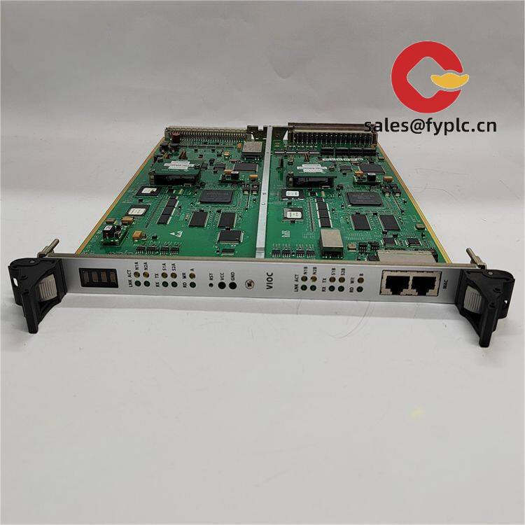
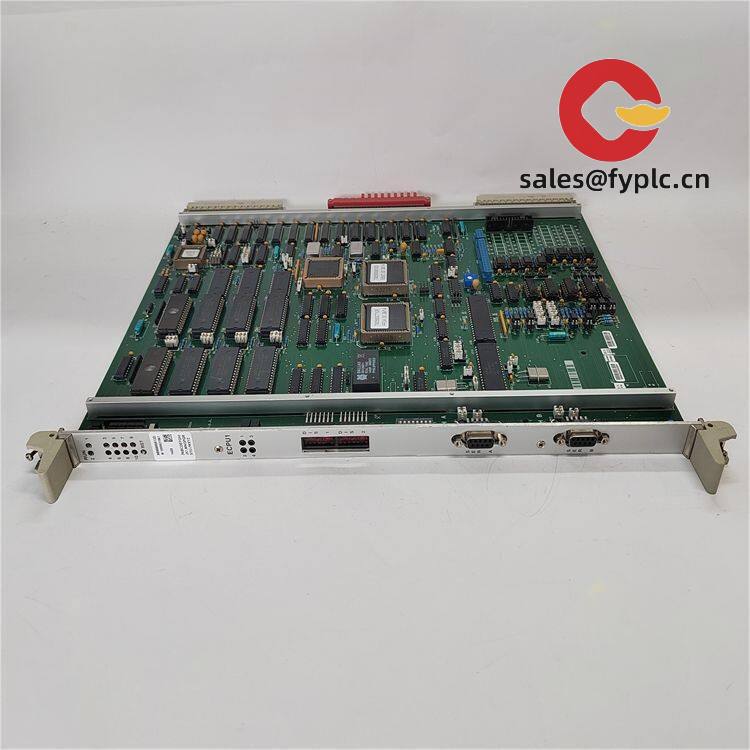
Alstom N897092520B–N897092057Y Propulsion Control PCB Set for Rolling Stock Maintenance
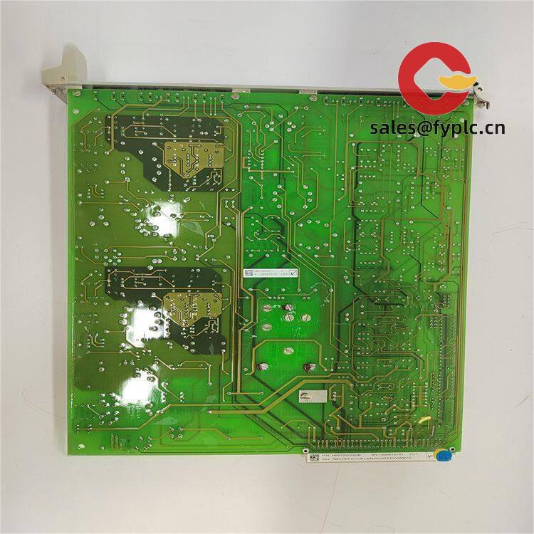
The Alstom N897092520B–N897092057Y combination is commonly supplied as a matched control/driver PCB set used inside traction converter or auxiliary converter racks on Alstom rolling stock. From my experience, these two boards are usually paired in the same bay and version-matched, so you reduce commissioning risks when you replace them together. For depots dealing with intermittent converter trips, irregular gate drive behavior, or converter self-diagnostics pointing to control-chain faults, this set typically brings the system back to stable service quickly.
Company’s Order Placement Process and Guarantees
- Warranty period: 365 days
- Delivery time: 1 week for in-stock; no more than one month at the latest
- Payment: 50% advance payment; full payment before delivery
- Express delivery: FedEx, UPS, DHL
- Pre-shipment checks: visual inspection, connector integrity, functional verification where applicable
Key Features
- Matched control/driver pair – Supplied as N897092520B and N897092057Y to maintain firmware and hardware compatibility inside Alstom converter racks.
- Railway-grade design – Built for vibration, surge, and temperature swings typical of rolling stock environments, often aligned with EN 50155 practices.
- Backplane integration – Plug-in PCB format that mates to the converter’s proprietary backplane for power, I/O and internal communications.
- Signal conditioning and protection – Opto-isolated I/O and guarded low-level analog sensing for stable control feedback in noisy traction bays.
- Service-friendly handling – Front access, captive fasteners, and clear test points make depot replacement faster; one customer told me their swap-and-test took under 30 minutes.
- Version support – Suffix codes “B” and “Y” typically indicate hardware/firmware revisions; we help verify interchangeability against your converter build list.
Technical Specifications
| Brand / Model | Alstom N897092520B–N897092057Y |
| Product Type | Propulsion control PCB set (converter control/driver modules) |
| HS Code | 8538.90 (Parts suitable for electrical control equipment) |
| Power Requirements | 24 VDC nominal (from vehicle auxiliary supply/backplane) |
| Operating Temperature | Typically −25°C to +70°C (railway service conditions) |
| Signal I/O Types | Opto-isolated digital I/O, low-level analog sense inputs, driver outputs to converter power stage |
| Communication Interfaces | Proprietary backplane bus; service/test headers for depot diagnostics |
| Installation Method | Plug-in PCB for converter rack; front-panel retention screws; keyed connectors |
| Form Factor | Board-level assembly; compact, rack-insertable footprint |
Application Fields
This pair is used in rolling stock propulsion and auxiliary systems where Alstom converter platforms are installed:
- Traction converters for EMU/METRO/Locomotive propulsion
- Auxiliary converters and static inverters on passenger or freight fleets
- Dynamic/braking chopper control sections
- Converter bays interfacing with TCMS and vehicle diagnostics
Advantages & Value
- High availability – We focus on hard-to-find Alstom spares, which typically shortens downtime and avoids prolonged parked units.
- Version matching support – You might notice suffix differences across fleets; we verify compatibility against your converter serial/build list before shipping.
- Reduced risk – Boards are inspected and electrically verified where applicable; 365‑day warranty provides practical assurance in service.
- Cost-efficient lifecycle – Procuring the pair often avoids repeat interventions caused by mixed revisions, saving both labor and commissioning trips.
Installation & Maintenance
- Environment – Install in the original converter rack with adequate ventilation; keep dust and metallic debris out of the bay.
- Handling – Observe ESD protection; do not touch conformal-coated areas or test points unnecessarily.
- Wiring – Seat the board fully into the backplane; tighten front-panel retention screws evenly; verify keyed connectors are aligned before power-up.
- Safety – Isolate 24 VDC auxiliary and lock out the traction system before removal or insertion; follow depot LOTO procedures.
- Routine checks – Periodically inspect connectors for oxidation, clean with approved contact cleaner, and review converter self-diagnostic logs.
- Firmware pairing – In many cases, control and driver boards must run matching firmware; we can pre-check or arrange updating if required.
Quality & Certifications
- Designed for railway environments aligned with EN 50155 and EN 50121-3-2 practices
- CE marking where applicable; produced under ISO 9001 quality systems
- RoHS compliance or permitted railway exemptions, depending on build date and revision
- Warranty: 365 days from delivery
If you can share your converter serial number, rack position, and the exact silk-screen/EPROM labels on your existing boards, we’ll confirm interchangeability and ship the correct N897092520B–N897092057Y pairing without delay.


Reviews
There are no reviews yet.