
Description
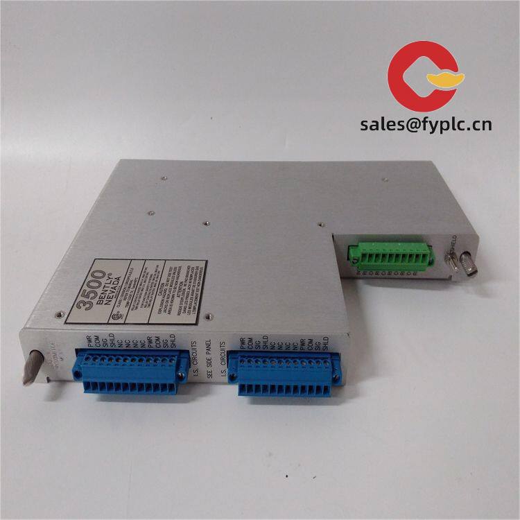
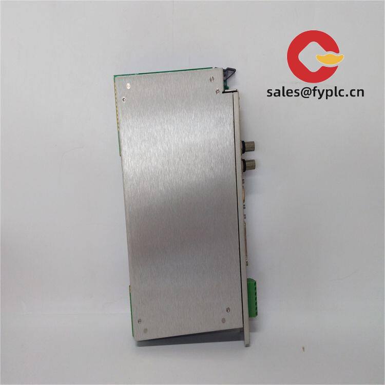
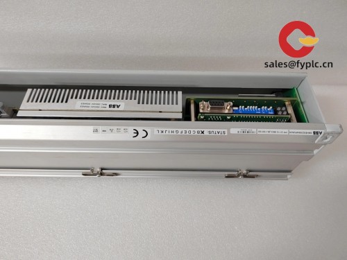
Bently Nevada 135462-01 – 16‑Channel Relay Module for 3500 Machinery Protection Racks
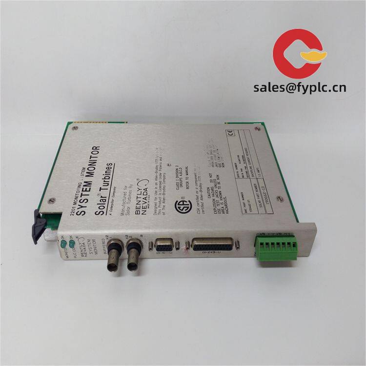
The Bently Nevada 135462-01 is a 16‑channel relay output module designed to turn vibration and condition monitoring events into hardwired actions—things like alarms, interlocks, and trips. From my experience with 3500 systems, this module is the go‑to when you need clean, deterministic relay contacts tied to well‑defined alarm logic, without adding a separate PLC or relay panel.
Company’s Order Placement Process and Guarantees
- Warranty: 365 days
- Delivery: 1 week if in stock; no more than 1 month at the latest
- Payment: 50% advance payment; full payment before delivery
- Express options: FedEx, UPS, DHL
Key Features
- 16 independent dry‑contact outputs – Each channel can be assigned to different alarm conditions from one or more monitors in the rack.
- Programmable alarm drive logic – AND/OR combinations, voting, latching or non‑latching behavior; typically configured via 3500 configuration software.
- Fail‑safe options – Normally de‑energized (common for trip circuits) or normally energized, depending on site standards.
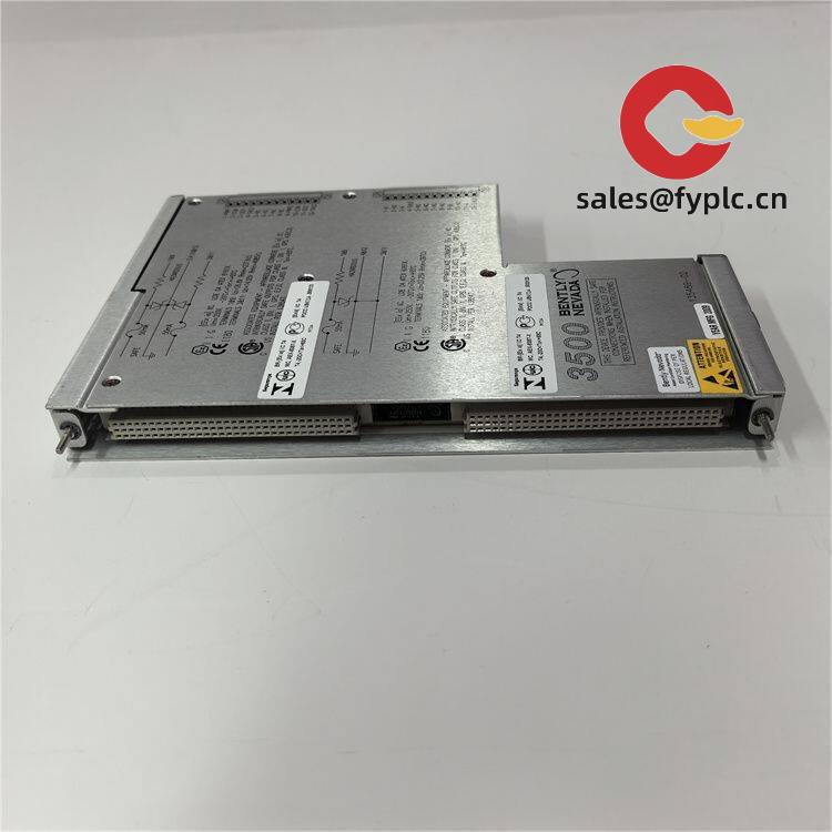
- Rack‑integrated – Uses the 3500 backplane; no external power supply or network configuration on the module itself.
- Event and status visibility – Works seamlessly with the 3500/22M TDI for System 1 connectivity, time‑stamped events, and Modbus mapping.
- Industrial relay terminals – Simple screw‑terminal I/O on the rear I/O module; easy to wire into ESD/PLC interlocks through interposing relays when needed.
- Designed for machinery protection – Commonly used to drive alarms and trips for turbines, compressors, high‑value pumps and fans.
Technical Specifications
| Brand / Model | Bently Nevada 135462-01 (16‑Channel Relay Module, 3500 Series) |
| HS Code | 9032.89 (Automatic regulating or controlling instruments and apparatus) |
| Power Requirements | Powered via 3500 rack backplane; no external supply required |
| Operating Temperature | Typically −30 °C to +65 °C (per 3500 system environmental ratings) |
| Signal I/O Types | 16 dry‑contact relay outputs; Form C style usage is common; supports latching/non‑latching and fail‑safe configurations |
| Communication Interfaces | Module is backplane‑based; network and software integration provided through 3500/22M TDI (System 1, Modbus) |
| Installation Method | Front module fits a single 3500 rack slot; rear I/O module with screw terminals for field wiring |
| Typical Use | Alarm and trip actuation based on vibration/condition alarms from multiple rack monitors |
Application Fields
You’ll usually see the 135462-01 in critical rotating equipment trains where hardwired trips still matter. Typical applications include:
- Steam and gas turbines – alarm/trip outputs to TMR ESD or turbine control systems
- Compressors and expanders – interlocks for high vibration or axial position
- Large pumps, fans, motors – local audible/visual alarms and MCC trips
- Refining, petrochemical, power generation – redundant interlocking with PLC/ESD via interposing relays
Advantages & Value
- Reliability – Relay logic runs inside the 3500 rack, which seems to be more predictable than external mapping through third‑party gear.
- Compatibility – Works with existing 3500 monitors and the 3500/22M TDI; configuration feels familiar if you already manage 3500 racks.
- Cost control – Reduces the need for extra relay panels; in many cases, you can wire straight to ESD using site‑standard interposing relays.
- Maintenance friendly – Clear channel mapping and front diagnostics typically make troubleshooting faster during turnarounds.
- Support – We can help with part matching, firmware alignment, and basic configuration notes to keep commissioning smooth.
Installation & Maintenance
- Cabinet & rack – Mount in a 3500 rack within a clean, ventilated cabinet. Maintain adequate airflow and follow recommended grounding practices.
- Wiring – Use shielded, twisted pairs for relay circuits where noise is a concern. For high energy loads, route through interposing relays and protect with fuses or breakers.
- Safety – Adopt fail‑safe logic for trip circuits (normally de‑energized) unless site standards dictate otherwise. Verify de‑energize‑to‑trip behavior during SAT.
- Configuration – Define alarm drive logic (AND/OR, voting, latching) in the 3500 configuration software and keep a controlled backup of the rack config.
- Routine checks – Function‑test relay outputs during scheduled outages; clean terminal blocks; review event logs in System 1; keep firmware and configuration aligned across the rack.
Quality & Certifications
- Compliance: CE marked; UL/cUL listings are typical for 3500 series modules; RoHS alignment on current production
- Manufacturer policy: Standard manufacturer warranty is typically 1 year
- Our coverage: 365‑day warranty as stated above
What users say
“We tied the 16 relays to a mix of axial position and velocity alarms, then voted them into the ESD. The bypass and latching options made commissioning a lot easier than using a separate relay rack.”
One thing I appreciate is how straightforward it is to map multiple monitor alarms to a single relay with voting. You might notice that this reduces nuisance trips during startups, especially when combined with trip‑multiply and time delays.


Reviews
There are no reviews yet.