
Description
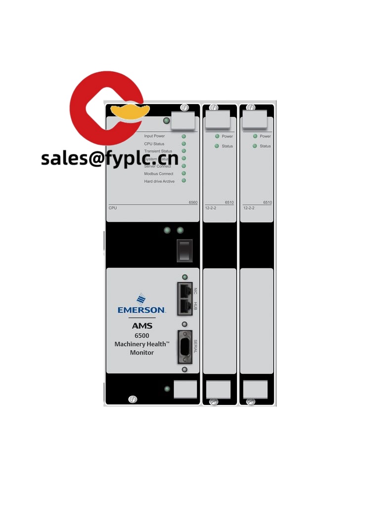
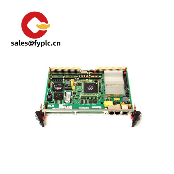
Emerson A6500-SR – Relay/Trip Module for the A6500 Machinery Protection System
The Emerson A6500-SR is the relay output module used in the A6500 rack to drive alarms and protective trips based on vibration, speed, and process limits. From my experience, plants use it to implement API 670-style voting logic and to create clean, dependable trip chains without adding external relay boxes. One thing I appreciate is how it centralizes trip logic inside the rack, which typically reduces wiring, troubleshooting time, and commissioning effort.
Order Placement Process & Guarantees
- Warranty: 365 days
- Lead time: 1 week if in stock; no more than 1 month at the latest
- Payment: 50% advance payment, full payment before delivery
- Express delivery: FedEx, UPS, DHL
Key Features
- Rack-integrated relay outputs – Receives alarm states from A6500 monitoring modules and provides dry-contact outputs for annunciation and trip.
- Voting logic support – Typically supports 1oo2, 2oo3, or similar voting, helping meet API 670 trip integrity practices without external logic relays.
- Fail-safe behavior – In many cases, relays can be configured as de-energize-to-trip, improving safety on power loss events.
- Latching and non-latching modes – Useful for combining alarm signaling with protection trips that require manual reset.
- Front-panel status indication – You might notice that local LEDs and clear channel labeling make maintenance checks faster during turnarounds.
- Backplane-powered – No separate power input; reduces wiring and keeps the panel tidy.
- Compatible with A6500 system tools – Configured via the A6500 rack environment; simplifies setup alongside vibration or speed channels.
Technical Specifications
| Brand / Model | Emerson A6500-SR |
| HS Code | 9032.89 (Automatic regulating or controlling instruments and apparatus) |
| Power Requirements | Powered via A6500 rack backplane; rack supply typically 24 VDC (approx. 18–36 VDC system range) |
| Dimensions & Weight | A6500 plug-in module format (approx. Eurocard 100 × 160 mm card depth); ~0.25–0.35 kg typical |
| Operating Temperature | 0 to +60 °C (storage typically -40 to +85 °C) |
| Signal I/O Types | Relay outputs (dry contact), commonly SPDT; configurable for alarm/trip, latching/non-latching. Contact rating typically up to 2 A @ 30 VDC (resistive). Galvanic isolation from rack logic. |
| Communication Interfaces | No direct field comms on the module; configured and supervised via the A6500 rack. System-level Modbus (TCP/RTU) available via the A6500 communications module. |
| Installation Method | Plug-in card for the Emerson A6500 19-inch rack; wiring via rack terminal blocks; secured by front-panel hardware. |
Note: Values above reflect typical characteristics for the A6500 series. Exact ratings can vary slightly by hardware revision.
Application Fields
- Oil & Gas turbomachinery protection (compressors, pumps, expanders) with API 670 practices
- Power generation (steam and gas turbines, balance-of-plant rotating assets)
- Petrochemical and chemical plants needing integrated alarm/trip logic
- Paper, metals, and mining facilities consolidating vibration trips into a central rack
- Water and wastewater stations where clean trip signaling and annunciation are required
A reliability engineer told us they swapped external trip relays for the A6500-SR during a modernization and, in most cases, cut cabinet wiring by a third. Fault-finding became simpler, since alarm states and trips were visible in the same software workspace as vibration channels.
Advantages & Value (Procurement View)
- System consistency – Keeps alarm/trip logic inside the A6500 rack, reducing third-party relay hardware and panel complexity.
- Lower lifecycle cost – Fewer external components typically mean fewer spares, fewer drawings to maintain, and less wiring to fail.
- Compatibility – Works natively with A6500 monitoring modules; voting, delay, and latching behaviors are aligned with system tools.
- Reduced downtime – Front-removable module makes replacement straightforward during outages or proof tests.
- Supportability – Emerson’s global footprint seems to be a strong point for plants standardizing on A6500.
Installation & Maintenance
- Cabinet & environment – Install the A6500 rack in a clean, ventilated 19-inch cabinet. Maintain ambient 0–60 °C and avoid high vibration panels when possible.
- Power & grounding – Provide a stable 24 VDC rack supply with proper protective earth. Keep relay commons and shields properly grounded to minimize noise.
- Wiring – Use shielded cable for trip circuits. Separate low-level signals from relay power lines. Clearly label NO/NC states and document latching behavior.
- Safety – For de-energize-to-trip configurations, verify trip state on loss of power. Implement lockout/tagout before rewiring trips.
- Routine checks – Perform periodic proof testing of each relay channel, verify voting logic (e.g., 2oo3), and back up the A6500 rack configuration after any change.
Quality & Certifications
- CE and RoHS compliant; UL/cUL recognition typically available for A6500 modules
- Designed for use in API 670-compliant protection architectures (system-level)
- Manufacturer warranty: 12 months (standard practice)
If you’re consolidating alarm and trip logic inside the A6500 rack, the A6500-SR is usually the cleanest way to do it—less cabinet clutter and better traceability of trip events. Happy to help verify channel counts and contact ratings against your P&IDs or cause-and-effect matrix.


Reviews
There are no reviews yet.