
Description
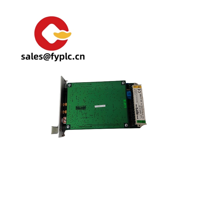
EPRO MMS6120 9100-00002-10 – Speed/Phase Module for MMS 6000 Machinery Protection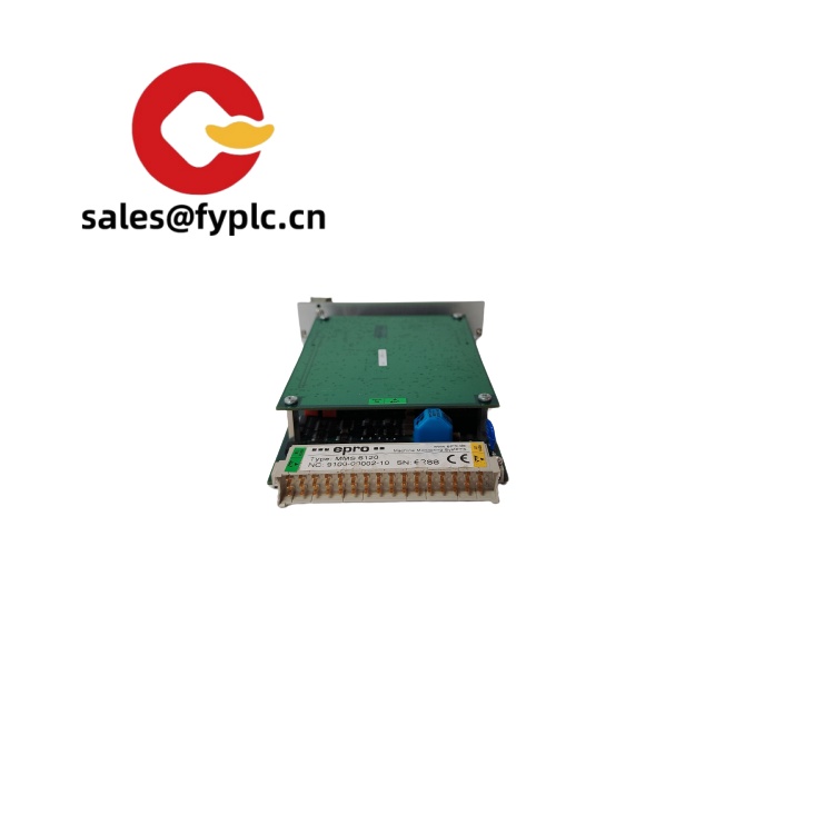
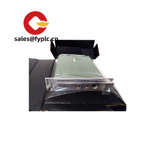
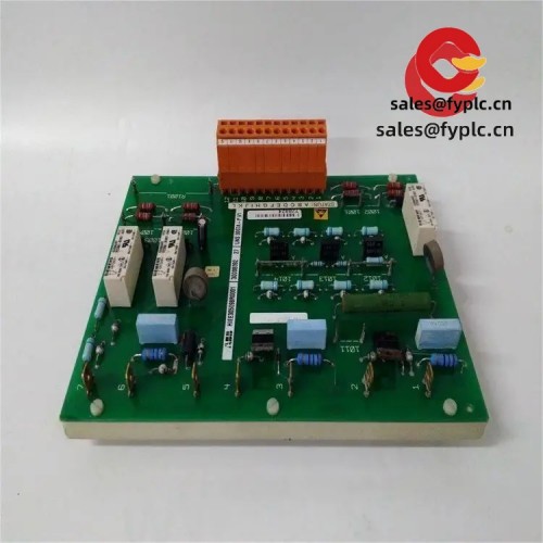
The EPRO MMS6120 (variant 9100-00002-10) is a plug-in speed/phase monitoring module for the MMS 6000 platform, typically used to deliver reliable shaft speed and phase reference signals for machinery protection and condition monitoring. From my experience, plants use the MMS6120 to generate a clean tachometer/keyphasor reference for vibration analysis and to support overspeed/alarm logic within the rack. It seems to be a practical choice when you’re standardizing on epro PR642x proximity probes or magnetic pickups and need stable triggering under varying run-up and run-down conditions.
One thing I appreciate is how it slots straight into existing MMS 6000 racks—no surprises in wiring or setup. You might notice that most installations pair the 6120 with eddy-current probes for precise phase tracking, then use the rack’s relays or 4–20 mA outputs for DCS trends and permissives. A maintenance planner told us they swapped a 6120 into an older MMS rack in under 15 minutes and immediately restored reliable speed tracking on a steam turbine after nuisance trips from a legacy tachometer.
Our Order Placement Process and Guarantees
- Warranty: 365 days
- Delivery: 1 week if in stock; no more than one month at the latest
- Payment: 50% advance payment; full payment before delivery
- Express logistics: FedEx, UPS, DHL
Key Features
- Dedicated speed/phase measurement – Provides a stable tachometer/keyphasor reference for synchronous vibration analysis and balancing.
- Compatible with common sensors – Typically accepts inputs from proximity probes (e.g., PR642x via appropriate driver) or magnetic pickups found on turbines, compressors, and large motors.
- Rack-integrated alarms – Works with MMS 6000 backplane for alarm voting, relays, and trip logic; minimizes extra panel hardware.
- Analog trending – In many cases provides 4–20 mA outputs at the rack level for DCS/PLC trend capture of speed or derived values.
- Robust triggering – Designed for clean phase detection across run-up/down, helping reduce false events when the signal-to-noise ratio isn’t perfect.
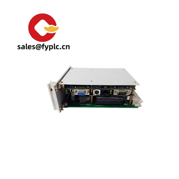
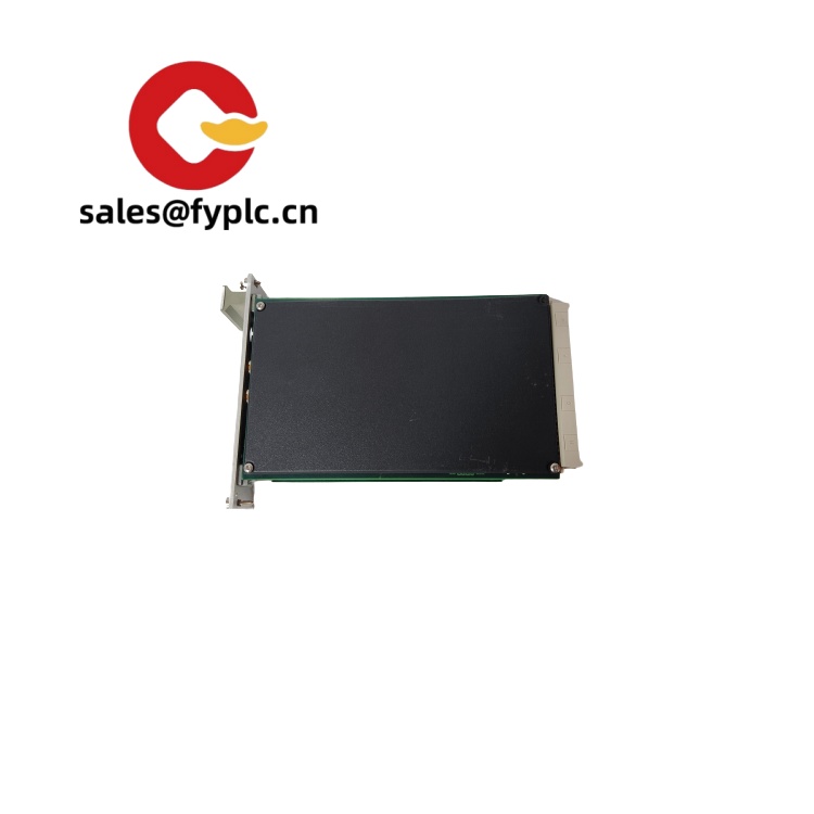
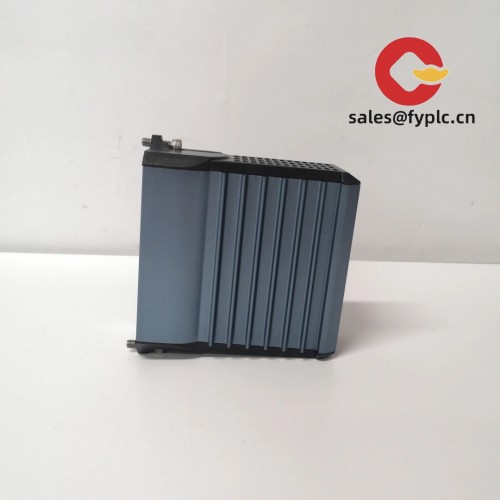
- Drop-in for MMS 6000 – Plug-in module; no special tools; keeps cabinet layouts standard and serviceable.
Technical Specifications
| Brand / Model | EPRO MMS6120 (9100-00002-10) |
| HS Code | 903289 (Other automatic regulating or controlling instruments) |
| Power Requirements | Powered via MMS 6000 backplane; rack supply typically 24 VDC (or AC supply via rack PSU) |
| Signal Inputs | Speed/phase (tachometer) input; commonly from proximity probe drivers or magnetic pickups (per option code) |
| Outputs | Alarm/status via rack; 4–20 mA and relays typically available at the MMS 6000 rack level |
| Communication | Integrated with MMS 6000 system bus; Modbus/serial gateways handled by the rack’s interface module |
| Installation Method | 3U plug-in card for MMS 6000 rack; cabinet mounting via 19″ rack or panel with adequate ventilation |
| Operating Temperature | Typically 0 to +55 °C (refer to specific data sheet for exact limits) |
| Dimensions & Weight | MMS 6000 plug-in module form factor (3U). Exact dimensions/weight per rack documentation |
Related or Supporting Products
- EPRO PR6422 / PR6423 proximity probes – Commonly used with MMS speed/phase and vibration channels; excellent for keyphasor generation.
- EPRO CON041 / CON011 drivers – Probe drivers for PR642x probes; ensure correct gap and signal levels for the MMS rack.
- EPRO MMS6110 vibration module – Pairs with the MMS6120 for synchronous vibration analysis and protection.
- EPRO MMS6312 overspeed/protection module – For applications requiring dedicated overspeed trips alongside speed/phase measurement.
- MMS 6000 power supply and interface modules – Provide rack power, relays, and Modbus/serial connectivity where required.
Installation & Maintenance
- Cabinet & environment – Mount MMS 6000 racks in clean, dry control cabinets with stable ambient temperature (typically 0–55 °C). Allow airflow; avoid mounting next to high-heat drives without separation.
- Wiring & shielding – Use individually shielded twisted pairs for probe and tachometer lines; ground shields at one end (rack side) to reduce noise. Keep sensor cables away from VFD outputs.
- Sensor setup – For proximity probes, set correct gap and target geometry; confirm clean once-per-rev mark for phase stability. For magnetic pickups, verify tooth/module count and adequate signal amplitude at low speed.
- Commissioning – Validate direction, phase marker polarity, and scaling. Trend speed on DCS via the 4–20 mA output if enabled at rack level.
- Routine maintenance – Inspect connectors quarterly, re-check probe gaps during outages, clean terminals, and review alarm/event logs. Firmware/config backups should be exported after any changes.
- Spares strategy – Keep at least one spare MMS6120 module and a matched probe/driver pair on hand for critical trains.
Quality & Certifications
- CE-marked for EMC and safety (typical for MMS 6000 series)
- RoHS-compliant components in most configurations
- Manufactured under ISO 9001 quality systems
- Manufacturer’s warranty support; our commercial warranty: 365 days
If you’re integrating this module into a mixed-sensor environment or replacing an older tachometer card, share your rack configuration and sensor type. We can double-check the 9100-00002-10 option against your probe/driver to ensure clean triggering and correct scaling on day one.


Reviews
There are no reviews yet.