
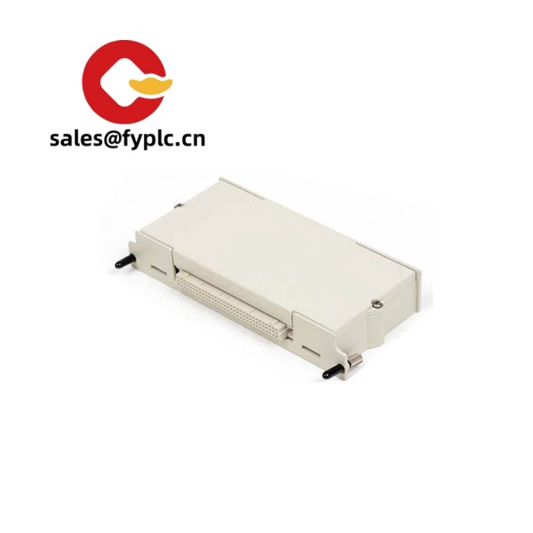
Description
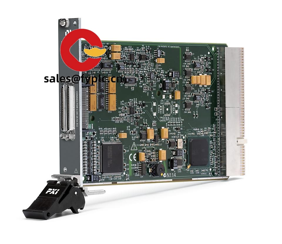
NI PXI‑2510 Fault Insertion Switch Module – Purpose‑built for HIL and Functional Test
The NI PXI‑2510 is a relay‑based fault insertion unit designed for automated test setups that need to simulate real‑world wiring faults—opens, shorts to ground, shorts to battery—without touching the device under test. From my experience, this module slots neatly into a PXI chassis and gives you controlled, repeatable fault scenarios for ECU validation, harness testing, and safety‑critical electronics. You might notice that it behaves like a standard NI switch module from a software point of view, so it’s quick to integrate with existing NI‑SWITCH code and LabVIEW/TestStand sequences.
Order Placement Process and Guarantees
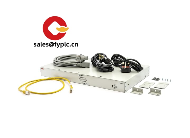
- Warranty period: 365 days
- Delivery time: typically 1 week if in stock; no more than one month at the latest
- Payment: 50% advance payment; full payment prior to delivery
- Express delivery options: FedEx, UPS, DHL
Key Features
- HIL‑grade fault insertion – Create opens and shorts (to GND or supply) on multiple lines to stress ECUs, wire harnesses, and control modules in a controlled way.
- PXI integration – Installs in a standard 3U, 1‑slot PXI chassis position; managed over the PXI backplane for tight timing with other DAQ, load, or stimulus modules.
- NI‑SWITCH software support – Works with NI‑SWITCH driver; easily scripted in LabVIEW, LabWindows/CVI, and TestStand. In many cases, existing switch code can be reused with minimal edits.
- Deterministic triggering – PXI trigger/clock resources allow synchronized fault events alongside measurements or stimulus, which typically shortens test time.
- Designed for automated systems – Front‑end wiring to your fixture or terminal block keeps the DUT interface neat; fault paths can be routed to system ground or a protected supply rail.
- Proven reliability – Relay‑based topology that, in most cases, handles frequent switching cycles common in long‑running validation campaigns.
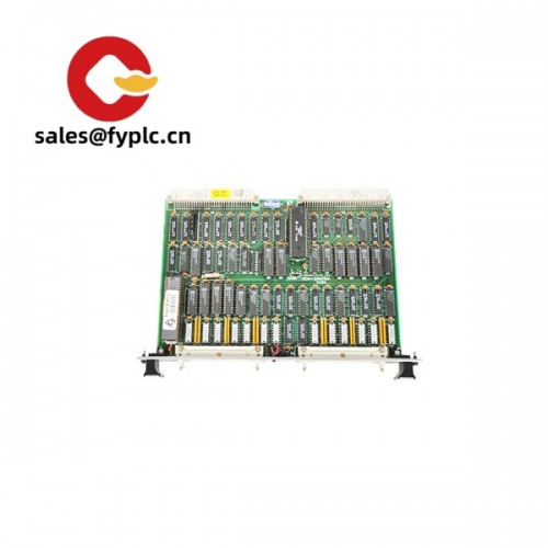
Technical Specifications
| Brand / Model | NI PXI‑2510 |
| HS Code | 8536.41 (Relays; typical classification for relay‑based switching modules) |
| Power Requirements | Powered via PXI backplane (3.3 V/5 V rails); typical consumption under 10 W |
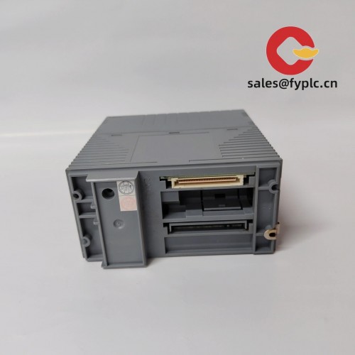
| Form Factor / Slot Usage | PXI 3U, 1‑slot module |
| Dimensions & Weight | Standard 3U PXI board; typical weight ~0.3–0.5 kg |
| Operating Temperature | 0 °C to 55 °C (typical PXI switch module rating) |
| Signal I/O Types | Relay‑based fault insertion paths enabling open circuits, short‑to‑GND, and short‑to‑supply configurations |
| Communication Interfaces | Control via PXI backplane; software through NI‑SWITCH API (LabVIEW, LabWindows/CVI, TestStand) |
| Installation Method | Direct plugin to a PXI or PXIe chassis with PXI‑compatible slots; front wiring to DUT/fixture |
Typical Use Cases
- ECU validation: inject opens on sensor lines or short actuators to ground to verify diagnostics and fail‑safe behavior.
- Harness/loom test: automate continuity checks and simulate pin‑to‑pin shorts during production test.
- Functional safety verification: trigger transient faults in sync with measurements to confirm ASIL‑aligned responses.
Related or Supporting Products
- NI PXI‑2511 – Similar fault insertion module with variant channel ratings; often chosen when higher isolation is required.
- NI PXI‑2512 – Fault insertion with differences in voltage/current capability; typically used for more demanding load lines.
- NI PXI‑2529 – High‑density matrix switch; not a fault insertion unit but handy for routing signals to measurement instruments in the same rack.
- PXI/PXIe Chassis – For example, PXI‑1085 or PXI‑1071; the PXI‑2510 fits any chassis providing PXI‑compatible 3U slots.
- Terminal blocks and cabling – Use NI high‑density terminal blocks and shielded cables matched to the 25xx series to keep fault paths clean and repeatable.
Installation & Maintenance
- Environment – Mount in a standard PXI chassis with adequate airflow; keep ambient within 0–55 °C and non‑condensing humidity.
- Wiring – Route DUT lines through the FIU’s front connector to defined fault rails (GND or protected supply). Use shielded, labeled harnesses; separate high‑current paths from sensitive analog lines.
- Safety – Protect supply rails with appropriate fusing/TVS where needed. Confirm the relay ratings versus your DUT voltage/current before running automated scripts.
- Software setup – Install NI‑SWITCH; verify module identity in NI MAX. From my experience, a brief continuity check routine saves a lot of time before full test runs.
- Routine care – Keep connectors clean, check screw terminations for torque after thermal cycles, and review relay counts in software to plan preventive maintenance on high‑usage channels.
Quality & Certifications
- CE and RoHS compliant; manufactured under ISO 9001 quality systems
- Manufacturer warranty typically applies; our coverage adds 365‑day support on supply
- Traceable serial identification for asset management in regulated labs
One thing I appreciate is how quickly teams get productive with the PXI‑2510: if you already use NI switching, this feels familiar on day one. If your setup has unusual voltage or current levels, share that up front—there are neighboring models (PXI‑2511/2512) that, in many cases, fit those edge conditions better.


Reviews
There are no reviews yet.