
Description
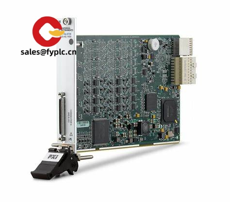
NI PXIe-6570 Digital Pattern Instrument – Vector-based digital test for semiconductor, IC, and board-level validation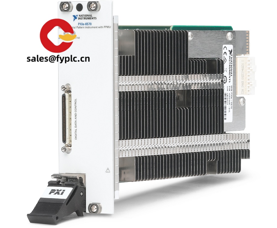
The NI PXIe-6570 is a PXI Express digital pattern instrument designed for pin-accurate, vector-based digital I/O. From my experience, it fits naturally into semiconductor device bring-up, mixed-signal ASIC validation, and high-throughput functional test where you need up to 100 MHz pattern rates with reliable compare results. You might notice that it scales cleanly for multi-site handlers and probers, yet it’s just as comfortable on a bench for SPI/I2C/UART interface testing, boot sequencing, and fast digital handshake with power instruments.
Order Placement Process & Guarantees
- Warranty: 365 days
- Lead time: 1 week if in stock; no more than one month at the latest
- Payment: 50% advance payment; full payment before delivery
- Shipping: FedEx, UPS, or DHL express
Key Features
- Vector-based digital patterns up to 100 MHz – Drive/compare per pin with tight timing for functional test and interface bring-up.
- Approx. 32-channel density per module – A practical sweet spot for single-site debug or multi-site production in PXIe chassis.
- Per-pin timing and levels – Define pin states, edges, and voltage levels by timing set; typically reduces rework when migrating from bench to handler.
- Onboard burst and failure capture – Pattern looping, conditional branching, and fail data logging speed up root-cause analysis.
- Backplane synchronization – Use PXI Express timing and triggers to sync with SMUs, scopes, or RF for mixed-signal scenarios.
- Software workflow that teams actually use – Develop with NI Digital Pattern Editor and niDigital driver; integrate in LabVIEW, TestStand, or Python/C# in many cases.
- High‑density front connectors – VHDCI-style digital breakout to your device interface board (DIB) keeps wiring compact and repeatable.
- Scales from bench to production – Common pattern assets and pin maps usually transfer with minimal edits.
A customer note: “We used PXIe‑6570 with an SMU to bring up a mixed-signal SoC. The digital boot pattern and SPI bring-up worked first week, and failure capture saved us hours when we mis-set a timing edge.” That tends to mirror what we see on early silicon projects.
Technical Specifications
| Brand / Model | NI (National Instruments) / PXIe-6570 |
| HS Code | 9030.82 – Instruments for measuring/checking semiconductor devices (typical classification) |
| Power Requirements | Powered by PXI Express backplane; no external power supply required |
| Form Factor / Size | 3U PXI Express plug‑in module; fits a standard PXIe chassis slot |
| Operating Temperature | 0 °C to 55 °C (typical for NI PXIe modules) |
| Signal I/O Types | Digital pattern I/O (drive/compare/tri‑state); approx. 32 channels per module |
| Front Connectors | High‑density VHDCI‑style connectors for breakout to DIB or fixture |
| Max Pattern Rate | Up to 100 MHz vector rate (per NI digital pattern architecture) |
| Communication / Control | PXI Express backplane; controlled via niDigital driver and Digital Pattern Editor |
| Installation Method | Plug into a PXIe chassis; connect front-panel to DUT through appropriate cable/DIB |
Related or Supporting Products
- NI PXIe-6571 – Newer-generation digital pattern instrument with higher performance and enhanced timing features; typically chosen when you need faster vector rates or tighter timing margins.
- NI PXI-6556 – High‑speed digital I/O (HSDIO) for arbitrary digital waveforms and acquisition; useful when you need protocol-flexible waveforms rather than vector-based burst/compare.
- NI PXIe-4139 – Precision SMU to source DUT power rails and run I‑V sweeps synchronized with digital patterns.
- NI PXIe-1085 chassis – High‑bandwidth PXIe chassis to host multi-site configurations and synchronize instruments over the backplane.
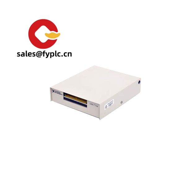
- NI SHC68‑series cables + CB/fixture or DIB – Typical VHDCI cabling from the PXIe‑6570 to a device interface board for reliable, repeatable connections.
Installation & Maintenance
- Chassis & slotting: Install the module in a PXI Express chassis with adequate cooling; keep intake/exhaust clear. From my experience, placing it near the system controller improves cable access to the DIB.
- Grounding & wiring: Use the recommended VHDCI cable and keep the DIB close to the chassis to minimize skew. Maintain solid ground returns and avoid long unterminated stubs on high‑speed pins.
- Trigger/sync: Use PXIe backplane triggers and reference clock to align bursts with SMUs, scopes, or other pattern instruments.
- Safety: Power down the system before mating front-panel connectors. Do not exceed specified per‑pin voltage/current limits; ESD protection for DUTs is strongly advised.
- Routine maintenance: Keep ventilation paths dust‑free; update niDigital drivers/firmware periodically; perform calibration on an annual or biennial schedule depending on your quality plan.
Quality & Certifications
- Conformity: CE and RoHS compliant; designed and manufactured under ISO 9001 quality systems (typical for NI).
- Documentation: Manufacturer datasheets and user manuals are available for safety, emissions, and EMC details.
- Warranty: 365‑day warranty from us; NI’s standard warranty policies may apply in addition depending on source and region.
Practical use case: validate an SoC boot sequence with the PXIe‑6570 driving reset and strap pins, while comparing readback vectors over SPI at 50–100 MHz. Synchronize with an SMU for rail ramping and capture failures on the exact vector cycle for fast debug.


Reviews
There are no reviews yet.