
Description
RENISHAW RMP400 – High-Accuracy Radio Spindle Probe for CNC Workpiece Setup and In‑Process Measurement
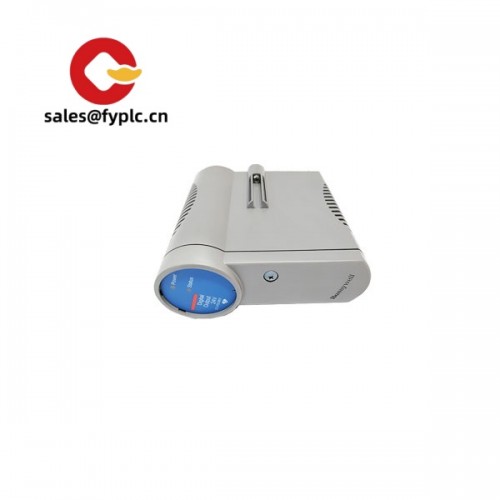
The RENISHAW RMP400 is a compact, strain‑gauge spindle probe with robust 2.4 GHz FHSS radio transmission. It’s built for tight-tolerance part setup and in‑process inspection on machining centers where optical line‑of‑sight isn’t reliable. From my experience, shops choose the RMP400 when they need small-probe form factor with the measurement stability of strain gauge technology—especially on 3D features, thin-walled parts, or when very low trigger forces help avoid part deflection.
Company’s Order Placement Process and Guarantees
- Warranty: 365 days
- Delivery: 1 week if in stock; no more than one month at the latest
- Payment terms: 50% advance payment; full payment prior to delivery
- Express options: FedEx, UPS, DHL
Key Features
- Strain‑gauge measurement core – Provides very stable 3D trigger behavior and low pre‑travel variation, typically improving repeatability on tight tolerances and angled surfaces.
- 2.4 GHz FHSS radio – Frequency‑hopping spread spectrum gives reliable probing in enclosed machines, even with coolant and chips bouncing around; no line‑of‑sight needed.
- Compact 40 mm body – Small probe envelope helps on smaller machining centers or when tool changer spaces are tight.
- Very low trigger forces – Reduces risk of part deflection on thin walls or micro-features; great for delicate workholding.
- Sealed for shop conditions – IP68‑level sealing (in most cases) stands up well to coolant, chips, and swarf.
- Battery powered, CNC‑friendly I/O – The probe runs on lithium cells, while the RMI/RMI‑Q interface presents simple discrete signals to your CNC, making integration straightforward.
- Flexible integration – Works with RENISHAW RMI or RMI‑Q, so you can run a single probe or multiple radio devices from one interface.
Customer remark: “We switched to the RMP400 to measure thin rib features on a 5‑axis job. The lighter touch and consistent triggers cut our rework noticeably. Radio sync has also been better in our large enclosure compared to optical.”
Technical Specifications
| Brand / Model | RENISHAW RMP400 |
| HS Code | 9031.80 (Measuring or checking instruments, n.e.s.) |
| Transmission | 2.4 GHz FHSS radio, license‑free band; compatible with RMI / RMI‑Q interfaces |
| Power Requirements | Probe: 2 × 1/2 AA 3.6 V lithium (Li‑SOCl2) batteries; Interface (RMI/RMI‑Q): 24 VDC |
| Dimensions & Weight | Approx. Ø40 mm body, ~50 mm length; ~240 g including batteries (typical) |
| Repeatability | Typically 0.25 μm (2σ) under standard test conditions |
| Operating Temperature | +5 °C to +50 °C (machine environment) |
| Ingress Protection | IP68‑level sealing (suitable for coolant environments) |
| Signal I/O Types | Probe trigger via RMI/RMI‑Q to CNC discrete input; status outputs and setup/enable via CNC I/O |
| Communication Interfaces | RENISHAW RMI or RMI‑Q (multi‑probe) machine interface |
| Stylus / Mounting | M4 stylus thread; spindle mounting via BT/CAT/HSK probe shanks |
| Typical Applications | Workpiece setup, 3D surface checks, in‑process measurement, post‑process verification |
Related or Supporting Products
- RENISHAW RMI – Single‑probe radio machine interface for the RMP series.
- RENISHAW RMI‑Q – Multi‑channel radio interface; typically allows multiple radio probes (e.g., spindle probe + tool setter) on one interface.
- RENISHAW RMP40 – Similar compact radio probe but with kinematic switch mechanism; good general purpose option when ultra‑low pre‑travel variation isn’t critical.
- RENISHAW OMP400 – Optical (infrared) version of the compact strain‑gauge probe; ideal when line‑of‑sight is available and optical is preferred.
- RENISHAW RMP600 – Larger strain‑gauge radio probe for extended stylus lengths and higher reach; same measurement principle with more body mass.
- M4 styli kits – Ruby ball styli (e.g., Ø4–6 mm) and low‑mass options for delicate surfaces.
Installation & Maintenance
- Mounting & alignment – Fit the RMP400 in a suitable BT/CAT/HSK probe shank and run the recommended on‑machine calibration macro to establish probe length/diameter and lobing compensation. You might notice best results using a short, rigid stylus first.
- Interface placement – Install the RMI or RMI‑Q inside the enclosure on a rigid bracket with clear “view” of the probe’s working area. Keep cables away from high‑noise drives; 24 VDC supply is typical.
- RF considerations – Avoid placing the interface directly behind thick splash guards or large masses of steel. In many cases, a small relocation dramatically improves signal margin.
- Wiring & I/O – Map the RMI trigger output to a free CNC input and use standard M‑codes/macros for probe enable/disable. If you use multiple radio devices, set unique channels on RMI‑Q.
- Safety & handling – Verify spindle is stopped before touching the probe. Use low jog speeds when testing new macros. Keep coolant jets from directly hammering the stylus during measurements.
- Routine care – Periodically inspect the stylus for wear, re‑calibrate after any crash or stylus change, and clean the shank taper. Battery changes are quick; replace cells as a pair and check seal integrity. Firmware/config updates (where applicable) should match your interface and macro set.
Quality & Certifications
- CE compliant; RoHS conform
- Manufactured under ISO 9001 quality systems
- Radio equipment designed for worldwide 2.4 GHz operation
- Manufacturer warranty: 12 months; our coverage: 365 days


Reviews
There are no reviews yet.